Engine. Toyota Rav4. Aca30, 33, 38 Gsa33 Zsa30, 35
DESCRIPTION
WIRING DIAGRAM
INSPECTION PROCEDURE
CHECK ENGINE SWITCH (SWITCH CONDITION)
CHECK WHETHER DTC OUTPUT OCCURS
CHECK CRANKING FUNCTION
READ VALUE USING INTELLIGENT TESTER (L CODE)
READ VALUE USING INTELLIGENT TESTER (ENGINE START CONDITION)
READ VALUE USING INTELLIGENT TESTER (S CODE)
REPLACE ID CODE BOX
READ VALUE USING INTELLIGENT TESTER (SHIFT LOCK CONTROL ECU)
READ VALUE USING INTELLIGENT TESTER (PARK/NEUTRAL POSITION SWITCH)
READ VALUE USING INTELLIGENT TESTER (STOP LIGHT SWITCH)
CHECK STEERING LOCK
CHECK MAIN BODY ECU (INSTRUMENT PANEL JUNCTION BLOCK)
CHECK SHIFT LOCK CONTROL ECU
CHECK HARNESS AND CONNECTOR (SHIFT LOCK CONTROL ECU - MAIN BODY ECU AND BODY GROUND)
INSPECT STARTER RELAY (ST)
INSPECT PARK/NEUTRAL POSITION SWITCH ASSEMBLY
CHECK HARNESS AND CONNECTOR (MAIN BODY ECU - PARK/NEUTRAL POSITION SWITCH)
CHECK HARNESS AND CONNECTOR (STARTER RELAY - PARK/NEUTRAL POSITION SWITCH AND BODY GROUND)
REPLACE STEERING LOCK ECU (STEERING LOCK ACTUATOR ASSEMBLY)
REPLACE ECU AGGREGATION BOX ASSEMBLY (CERTIFICATION ECU)
READ VALUE USING INTELLIGENT TESTER (CLUTCH START SWITCH)
CHECK STEERING LOCK
CHECK MAIN BODY ECU (INSTRUMENT PANEL JUNCTION BLOCK)
INSPECT STARTER RELAY (ST)
INSPECT CLUTCH START SWITCH
CHECK HARNESS AND CONNECTOR (MAIN BODY ECU - CLUTCH START SWITCH)
CHECK HARNESS AND CONNECTOR (STARTER RELAY - CLUTCH START SWITCH AND BODY GROUND)
ENTRY AND START SYSTEM - Engine does not Start |
DESCRIPTION
| ENGINE START SYSTEM OPERATION |
When the engine switch is pressed with the brake pedal (except M/T) or clutch pedal (for M/T) depressed and the shift lever in P or N (except M/T), the main body ECU determines that it is an engine start request.
The certification ECU and other ECUs perform key verification via the LIN communication line.
The main body ECU activates the ACC relay.
The main body ECU activates the IG1 and IG2 relays. The engine switch indicator light illuminates in green.
The certification ECU outputs a steering unlock signal. The signal is sent to the steering lock ECU via the main body ECU.
The main body ECU sends an engine start request signal to the ECM.
The ECM sends an ACC cut request signal to the main body ECU.
The ECM and main body ECU activate the ST cut relay.
The main body ECU deactivates the ACC relay until the ECU detects an engine start.
The ECU reactivates the ACC relay and turns off the engine switch indicator light.
Symbol of Main Body ECU
| Signal
|
SSW1/SSW2
| Engine switch on (ACC) and on (IG) signal
|
ACCD
| ACC relay operation signal
|
IG2D
| IG2 relay operation signal
|
STR2
| ST cut relay operation signal
|
STR
| Park/neutral position switch (except M/T) or clutch start switch (for M/T) signal
|
STP (except M/T)
| Stop light switch signal
|
TACH
| Engine start detection signal
|
STSW
| Starter activation request signal
|
ACCR
| ACC cut request signal
|

WIRING DIAGRAM
Refer to Cranking Holding Function Circuit (RAV4_ACA30 RM000001FLC03TX.html).
INSPECTION PROCEDURE
| 1.CHECK ENGINE SWITCH (SWITCH CONDITION) |
Check the power source mode change.
When the key is inside the vehicle and the shift lever is in P (except M/T), check that pressing the engine switch causes the power source mode to change as follows:
- OK:
- off → on (ACC) → on (IG) → off
| 2.CHECK WHETHER DTC OUTPUT OCCURS |
Clear the DTCs (RAV4_ACA30 RM000000YEH04NX.html).
Check whether the trouble recurs 5 seconds after the engine switch is turned on (IG).
Check whether DTCs for the main body ECU or certification ECU are output.
ResultDTC Output
System Name
| Proceed to
|
No DTC output
| A
|
DTC for main body ECU output
Entry and start system
| B
|
DTC for certification ECU output
Steering lock system
| C
|
DTC for certification ECU output
Engine immobiliser system (w/ Entry and Start System)
| D
|
| 3.CHECK CRANKING FUNCTION |
Check the engine cranking function.
When there is fuel in the fuel tank, the key is inside the vehicle and the shift lever is in P (except M/T), check that depressing the brake pedal (except M/T) or clutch pedal (for M/T) and pressing the engine switch causes the engine to crank.
ResultResult
| Proceed to
|
Engine cranks
| A
|
Engine does not crank (except M/T)
| B
|
Engine does not cranks (for M/T)
| C
|
| 4.READ VALUE USING INTELLIGENT TESTER (L CODE) |
Connect the intelligent tester to the DLC3.
Turn the engine switch on (IG) and turn the intelligent tester on.
Enter the following menus: Body / Main Body / Data List.
Read the display on the intelligent tester.
Entry&StartTester Display
| Measurement Item/Range
| Normal Condition
| Diagnostic Note
|
L Code Check
| L code certification result/NG or OK
| OK: L code certification result normal
NG: L code certification result abnormal
| -
|
- OK:
- OK is displayed on the intelligent tester.
| 5.READ VALUE USING INTELLIGENT TESTER (ENGINE START CONDITION) |
Connect the intelligent tester to the DLC3.
Turn the engine switch on (IG) and turn the intelligent tester on.
Enter the following menus: Body / Main Body / Data List.
Read the display on the intelligent tester.
Entry&StartTester Display
| Measurement Item/Range
| Normal Condition
| Diagnostic Note
|
Engine Start Condition
| Engine start permission determined by certification ECU/OK or NG
| OK: Engine start permitted
NG: Engine start prohibited
| -
|
- OK:
- When the brake pedal (except M/T) or clutch pedal (for M/T) is depressed with the key inside the vehicle, OK is displayed on the intelligent tester.
| 6.READ VALUE USING INTELLIGENT TESTER (S CODE) |
Connect the intelligent tester to the DLC3.
Turn the engine switch on (IG) and turn the intelligent tester on.
Enter the following menus: Body / Main Body / Data List.
Read the display on the intelligent tester.
Entry&StartTester Display
| Measurement Item/Range
| Normal Condition
| Diagnostic Note
|
S Code Check
| S code certification result/NG or OK
| OK: S code certification result normal
NG: S code certification result abnormal
| -
|
- OK:
- OK is displayed on the intelligent tester.
Replace the ID code box (immobiliser code ECU).
Register the recognition code (ECU code).
Check that the engine starts.
- OK:
- Engine starts.
| 8.READ VALUE USING INTELLIGENT TESTER (SHIFT LOCK CONTROL ECU) |
Connect the intelligent tester to the DLC3.
Turn the engine switch on (IG) and turn the intelligent tester on.
Enter the following menus: Body / Main Body / Data List.
Read the display on the intelligent tester.
Main BodyTester Display
| Measurement Item/Range
| Normal Condition
| Diagnostic Note
|
Shift P Signal
| Shift lever P position signal/ON or OFF
| ON: Shift lever in P
OFF: Shift lever not in P
| -
|
- OK:
- ON (shift lever in P) and OFF (shift lever not in P) are displayed on the intelligent tester.
| 9.READ VALUE USING INTELLIGENT TESTER (PARK/NEUTRAL POSITION SWITCH) |
Connect the intelligent tester to the DLC3.
Turn the engine switch on (IG) and turn the intelligent tester on.
Enter the following menus: Body / Main Body / Data List.
Read the display on the intelligent tester.
Main BodyTester Display
| Measurement Item/Range
| Normal Condition
| Diagnostic Note
|
Neutral SW/ Clutch SW
| Park/neutral position switch/ON or OFF
| ON: Shift lever in P or N
OFF: Shift lever not in P or N
| -
|
- OK:
- ON (shift lever in P or N) and OFF (shift lever not in P or N) are displayed on the intelligent tester.
| 10.READ VALUE USING INTELLIGENT TESTER (STOP LIGHT SWITCH) |
Connect the intelligent tester to the DLC3.
Turn the engine switch on (IG) and turn the intelligent tester on.
Enter the following menus: Body / Main Body / Data List.
Read the display on the intelligent tester.
Main BodyTester Display
| Measurement Item/Range
| Normal Condition
| Diagnostic Note
|
Stop Light SW
| Stop light switch/ON or OFF
| ON: Brake pedal depressed
OFF: Brake pedal released
| -
|
- OK:
- ON (brake pedal is depressed) and OFF (brake pedal is released) are displayed on the intelligent tester.
Check if the steering lock is released when turning the engine switch on (ACC).
- OK:
- The steering lock is released.
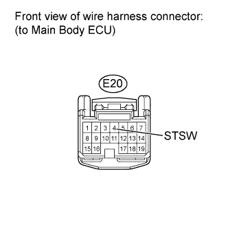
| 12.CHECK MAIN BODY ECU (INSTRUMENT PANEL JUNCTION BLOCK) |
Disconnect the E20 main body ECU connector.
Measure the voltage according to the value(s) in the table below.
- HINT:
- The voltage is generated at terminal STSW for 0.3 seconds when the engine cranks.
- Standard Voltage:
Tester Connection
| Condition
| Specified Condition
|
E20-4 (STSW) - Body ground
| Brake pedal depressed with shift lever in P or N and engine switch pushed once
| 11 to 14 V
|
| | REPLACE MAIN BODY ECU (INSTRUMENT PANEL JUNCTION BLOCK) |
|
|
| 13.CHECK SHIFT LOCK CONTROL ECU |
Disconnect the E44 shift lock control ECU connector.
Measure the resistance according to the value(s) in the table below.
- Standard Resistance:
Tester Connection
| Condition
| Specified Condition
|
7 (P2) - 1 (E)
| Shift lever not in P
| Below 1 Ω
|
7 (P2) - 1 (E)
| Shift lever in P
| 10 kΩ or higher
|
| 14.CHECK HARNESS AND CONNECTOR (SHIFT LOCK CONTROL ECU - MAIN BODY ECU AND BODY GROUND) |
Disconnect the E18 main body ECU connector.
Disconnect the E44 shift lock control ECU connector.
Measure the resistance according to the value(s) in the table below.
- Standard Resistance:
Tester Connection
| Condition
| Specified Condition
|
E18-15 (P) - E44-7 (P2)
| Always
| Below 1 Ω
|
E44-1 (E) - Body ground
| Always
| Below 1 Ω
|
E18-15 (P) or E44-7 (P2) - Body ground
| Always
| 10 kΩ or higher
|
| | REPAIR OR REPLACE HARNESS OR CONNECTOR |
|
|
| OK |
|
|
|
| REPLACE MAIN BODY ECU (INSTRUMENT PANEL JUNCTION BLOCK) |
|
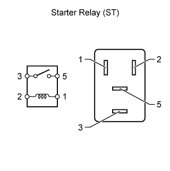
| 15.INSPECT STARTER RELAY (ST) |
Remove the starter relay from the No. 7 relay block (for LHD) or No. 8 relay block (for RHD).
Measure the resistance according to the value(s) in the table below.
- Standard Resistance:
Tester Connection
| Condition
| Specified Condition
|
3 - 5
| Battery voltage applied to terminals 1 and 2
| Below 1 Ω
|
3 - 5
| Battery voltage not applied to terminals 1 and 2
| 10 kΩ or higher
|
| 16.INSPECT PARK/NEUTRAL POSITION SWITCH ASSEMBLY |
Disconnect the park/neutral position switch connector.
Measure the resistance according to the value(s) in the table below.
- Standard Resistance:
Tester Connection
| Switch Condition
| Specified Condition
|
4 (B) - 9 (L)
| P
| Below 1 Ω
|
4 (B) - 9 (L)
| N
| Below 1 Ω
|
4 (B) - 9 (L)
| Not in P or N
| 10 kΩ or higher
|
| 17.CHECK HARNESS AND CONNECTOR (MAIN BODY ECU - PARK/NEUTRAL POSITION SWITCH) |
Disconnect the E20 ECU connector.
Disconnect the B28 switch connector.
Measure the resistance according to the value(s) in the table below.
- Standard Resistance:
Tester Connection
| Condition
| Specified Condition
|
E20-3 (STR) - B28-4 (B)
| Always
| Below 1 Ω
|
E20-3 (STR) or B28-4 (B) - Body ground
| Always
| 10 kΩ or higher
|
| | REPAIR OR REPLACE HARNESS OR CONNECTOR |
|
|
| 18.CHECK HARNESS AND CONNECTOR (STARTER RELAY - PARK/NEUTRAL POSITION SWITCH AND BODY GROUND) |
Measure the resistance according to the value(s) in the table below.
- Standard Resistance:
Tester Connection
| Condition
| Specified Condition
|
B28-9 (L) - Relay block ST relay terminal 1
| Always
| Below 1 Ω
|
B28-9 (L) or Relay block ST relay terminal 1 - Body ground
| Always
| 10 kΩ or higher
|
Relay block ST relay terminal 2 - Body ground
| Always
| Below 1 Ω
|
| | REPAIR OR REPLACE HARNESS OR CONNECTOR |
|
|
| OK |
|
|
|
| REPLACE MAIN BODY ECU (INSTRUMENT PANEL JUNCTION BLOCK) |
|
| 19.REPLACE STEERING LOCK ECU (STEERING LOCK ACTUATOR ASSEMBLY) |
Replace the steering lock actuator assembly (steering lock ECU).
- HINT:
- for LHD: refer to RAV4_ACA30 RM000000UCZ01WX.html.
- for RHD: refer to RAV4_ACA30 RM000000UCZ01XX.html.
Register the recognition code (ECU code).
- HINT:
- Refer to Service Bulletin.
Check that the engine starts.
- OK:
- Engine starts.
| 20.REPLACE ECU AGGREGATION BOX ASSEMBLY (CERTIFICATION ECU) |
Replace the certification ECU.
Register the recognition code (ECU code).
- HINT:
- Refer to Service Bulletin.
Check that the engine starts.
- OK:
- Engine starts.
| 21.READ VALUE USING INTELLIGENT TESTER (CLUTCH START SWITCH) |
Connect the intelligent tester to the DLC3.
Turn the engine switch on (IG) and turn the intelligent tester on.
Enter the following menus: Body / Main Body / Data List.
Read the display on the intelligent tester.
Main BodyTester Display
| Measurement Item/Range
| Normal Condition
| Diagnostic Note
|
Neutral SW/ Clutch SW
| Clutch start switch/ON or OFF
| ON: Clutch pedal depressed
OFF: Clutch pedal released
| -
|
- OK:
- ON (clutch pedal depressed) and OFF (clutch pedal released) are displayed on the intelligent tester.
Check if the steering lock is released when turning the engine switch on (ACC).
- OK:
- The steering lock is released.
| 23.CHECK MAIN BODY ECU (INSTRUMENT PANEL JUNCTION BLOCK) |
Disconnect the E20 main body ECU connector.
Measure the voltage according to the value(s) in the table below.
- HINT:
- The voltage is generated at terminal STSW for 0.3 seconds when the engine cranks.
- Standard Voltage:
Tester Connection
| Condition
| Specified Condition
|
E20-4 (STSW) - Body ground
| Clutch pedal depressed and engine switch pushed once
| 11 to 14 V
|
| | REPLACE MAIN BODY ECU (INSTRUMENT PANEL JUNCTION BLOCK) |
|
|
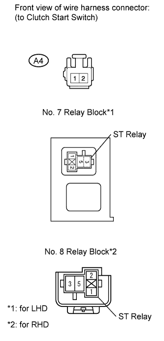
| 24.INSPECT STARTER RELAY (ST) |
Remove the starter relay from the No. 7 relay block (for LHD) or No. 8 relay block (for RHD).
Measure the resistance according to the value(s) in the table below.
- Standard Resistance:
Tester Connection
| Condition
| Specified Condition
|
3 - 5
| Battery voltage applied to terminals 1 and 2
| Below 1 Ω
|
3 - 5
| Battery voltage not applied to terminals 1 and 2
| 10 kΩ or higher
|
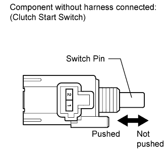
| 25.INSPECT CLUTCH START SWITCH |
Disconnect the clutch start switch connector.
Measure the resistance according to the value(s) in the table below.
- Standard Resistance:
Tester Connection
| Condition
| Specified Condition
|
1 - 2
| Clutch start switch pin pushed
| Below 1 Ω
|
1 - 2
| Clutch start switch pin not pushed
| 10 kΩ or higher
|
| | REPLACE CLUTCH START SWITCH |
|
|
| 26.CHECK HARNESS AND CONNECTOR (MAIN BODY ECU - CLUTCH START SWITCH) |
Disconnect the E20 ECU connector.
Disconnect the A4 switch connector.
Measure the resistance according to the value(s) in the table below.
- Standard Resistance:
Tester Connection
| Condition
| Specified Condition
|
E20-3 (STR) - A4-2
| Always
| Below 1 Ω
|
E20-3 (STR) or A4-2 - Body ground
| Always
| 10 kΩ or higher
|
| | REPAIR OR REPLACE HARNESS OR CONNECTOR |
|
|
| 27.CHECK HARNESS AND CONNECTOR (STARTER RELAY - CLUTCH START SWITCH AND BODY GROUND) |
Measure the resistance according to the value(s) in the table below.
- Standard Resistance:
Tester Connection
| Condition
| Specified Condition
|
A4-1 - Relay block ST relay terminal 1
| Always
| Below 1 Ω
|
A4-1 or Relay block ST relay terminal 1 - Body ground
| Always
| 10 kΩ or higher
|
Relay block ST relay terminal 2 - Body ground
| Always
| Below 1 Ω
|
| | REPAIR OR REPLACE HARNESS OR CONNECTOR |
|
|
| OK |
|
|
|
| REPLACE MAIN BODY ECU (INSTRUMENT PANEL JUNCTION BLOCK) |
|