Engine. Toyota Rav4. Aca30, 33, 38 Gsa33 Zsa30, 35
DESCRIPTION
WIRING DIAGRAM
INSPECTION PROCEDURE
READ VALUE USING INTELLIGENT TESTER (STARTER SIGNAL)
CHECK ECM (STSW TERMINAL VOLTAGE)
CHECK CLUTCH START SWITCH ASSEMBLY (INPUT VOLTAGE)
INSPECT CLUTCH START SWITCH ASSEMBLY
CHECK PARK/NEUTRAL POSITION SWITCH (INPUT VOLTAGE)
INSPECT PARK/NEUTRAL POSITION SWITCH
CHECK HARNESS AND CONNECTOR (ECM - MAIN BODY ECU)
INSPECT ST CUT RELAY
CHECK HARNESS AND CONNECTOR (ST CUT RELAY - BODY GROUND)
CHECK HARNESS AND CONNECTOR (ST CUT RELAY - IGNITION RELAY NO. 2 (IG2))
CHECK HARNESS AND CONNECTOR (ST CUT RELAY - ECM)
CHECK HARNESS AND CONNECTOR (ST CUT RELAY - MAIN BODY ECU)
CHECK HARNESS AND CONNECTOR (MAIN BODY ECU - CLUTCH START SWITCH ASSEMBLY)
CHECK HARNESS AND CONNECTOR (MAIN BODY ECU - PARK/NEUTRAL POSITION SWITCH)
CHECK ST RELAY (INPUT VOLTAGE)
INSPECT ST RELAY
CHECK HARNESS AND CONNECTOR (ST RELAY - BODY GROUND)
CHECK ST RELAY (INPUT VOLTAGE)
CHECK HARNESS AND CONNECTOR (ST RELAY - STARTER)
INSPECT STARTER
SFI SYSTEM - Cranking Holding Function Circuit |
DESCRIPTION
The cranking holding control system continues providing power to the ST relay after the ECM detects the starter signal (STSW signal) from the main body ECU until the ECM determines that the engine started. Furthermore, the ECM outputs an accessory cut signal (ACCR signal) to the ACC relay during cranking to prevent flickering of the combination meter, clock, audio system, and other areas.When the ECM detects the STSW signal, the ECM outputs the starter relay drive signal (STAR signal) to the starter relay through the park/neutral position switch (for CVT) or clutch start switch (for Manual Transaxle), and then the engine is cranked. When the ECM receives a stable engine speed signal (NE signal) (more specifically, when the NE signal reaches a predetermined value), the ECM stops outputting the STAR signal. Also, the ECM monitors the ST relay operating conditions based on the STA terminal voltage status.
WIRING DIAGRAM
INSPECTION PROCEDURE
- NOTICE:
- Inspect the fuses for circuits related to this system before performing the following inspection procedure.
| 1.READ VALUE USING INTELLIGENT TESTER (STARTER SIGNAL) |
Connect the intelligent tester to the DLC3.
Turn the ignition switch to ON and turn the tester on.
Enter the following menus: Powertrain / Engine and ECT / Data List / Starter Signal.
Check the result when the ignition switch is turned to ON, and when the engine is cranking.
- OK:
Condition
| Tester Display (Starter Signal)
|
Ignition switch ON
| OFF
|
Engine cranking
| ON
|
ResultResult
| Proceed to
|
NG
| A
|
OK
| B
|
| 2.CHECK ECM (STSW TERMINAL VOLTAGE) |
Disconnect the ECM connector.
Depress the clutch pedal fully (for Manual Transaxle).
Move the shift lever to N (for CVT).
Measure the voltage according to the value(s) in the table below.
- Standard Voltage:
Tester Connection
| Condition
| Specified Condition
|
A12-29 (STSW) - Body ground
| Engine starts
| 11 to 14 V
|
- HINT:
- The engine does not crank because the terminal is not connected.
ResultResult
| Proceed to
|
OK (for Manual Transaxle)
| A
|
OK (for CVT)
| B
|
NG
| C
|
Reconnect the ECM connector.
| 3.CHECK CLUTCH START SWITCH ASSEMBLY (INPUT VOLTAGE) |
Disconnect the clutch start switch assembly connector.
Measure the voltage according to the value(s) in the table below.
- Standard Voltage:
Tester Connection
| Condition
| Specified Condition
|
A4-2 - Body ground
| Engine cranking
| 11 to 14 V
|
Text in Illustration*1
| Front view of wire harness connector
(to Clutch Start Switch Assembly)
|
- HINT:
- The engine does not crank because the terminal is not connected.
Reconnect the clutch start switch assembly connector.
| 4.INSPECT CLUTCH START SWITCH ASSEMBLY |
Remove the clutch start switch assembly.
Measure the resistance according to the value(s) in the table below.
- Standard Resistance:
Tester Connection
| Switch Condition
| Specified Condition
|
1 - 2
| Pushed
| Below 1 Ω
|
1 - 2
| Not pushed
| 10 kΩ or higher
|
Reinstall the clutch start switch assembly.
| OK |
|
|
|
| REPAIR OR REPLACE HARNESS OR CONNECTOR (CLUTCH START SWITCH ASSEMBLY - ECM) |
|
| 5.CHECK PARK/NEUTRAL POSITION SWITCH (INPUT VOLTAGE) |
Disconnect the park/neutral position switch connector.
Measure the voltage according to the value(s) in the table below.
- Standard Voltage:
Tester Connection
| Condition
| Specified Condition
|
B28-4 - Body ground
| Engine cranking
| 11 to 14 V
|
Text in Illustration*1
| Front view of wire harness connector
(to Park/Neutral Position Switch)
|
- HINT:
- The engine does not crank because the terminal is not connected.
Reconnect the park/neutral position switch connector.
| 6.INSPECT PARK/NEUTRAL POSITION SWITCH |
Inspect the park/neutral position switch (RAV4_ACA30 RM00000191B01KX.html).
| OK |
|
|
|
| REPAIR OR REPLACE HARNESS OR CONNECTOR (PARK/NEUTRAL POSITION SWITCH - ECM) |
|
| 7.CHECK HARNESS AND CONNECTOR (ECM - MAIN BODY ECU) |
Disconnect the main body ECU connector.
Disconnect the ECM connector.
Measure the resistance according to the value(s) in the table below.
- Standard Resistance:
Tester Connection
| Condition
| Specified Condition
|
E20-4 (STSW) - A12-29 (STSW)
| Always
| Below 1 Ω
|
E20-4 (STSW) or A12-29 (STSW) - Body ground
| Always
| 10 kΩ or higher
|
Text in Illustration*1
| Front view of wire harness connector
(to Main Body ECU)
|
*2
| Front view of wire harness connector
(to ECM)
|
Reconnect the main body ECU connector.
Reconnect the ECM connector.
| | REPAIR OR REPLACE HARNESS OR CONNECTOR (ECM - MAIN BODY ECU) |
|
|
Remove the ST CUT relay from the No. 7 relay block.
Measure the resistance according to the value(s) in the table below.
- Standard Resistance:
Tester Connection
| Condition
| Specified Condition
|
3 - 5
| Battery voltage not applied to terminal 1 and 2
| 10 kΩ or higher
|
3 - 5
| Battery voltage applied to terminal 1 and 2
| Below 1 Ω
|
Reinstall the relay.
| 9.CHECK HARNESS AND CONNECTOR (ST CUT RELAY - BODY GROUND) |
Remove the ST CUT relay from the No. 7 relay block.
Measure the resistance according to the value(s) in the table below.
- Standard Resistance:
Tester Connection
| Condition
| Specified Condition
|
ST CUT relay terminal 1 - Body ground
| Always
| Below 1 Ω
|
Text in Illustration*1
| No. 7 Relay Block
|
*2
| ST CUT
|
Reinstall the ST CUT relay.
| | REPAIR OR REPLACE HARNESS OR CONNECTOR (ST CUT RELAY - BODY GROUND) |
|
|
| 10.CHECK HARNESS AND CONNECTOR (ST CUT RELAY - IGNITION RELAY NO. 2 (IG2)) |
Remove the ST CUT relay from the No. 7 relay block.
Remove the ignition relay No. 2 (IG2) from the engine room No. 1 relay block.
Measure the resistance according to the value(s) in the table below.
- Standard Resistance (Check for Open):
Tester Connection
| Condition
| Specified Condition
|
Ignition relay No. 2 (IG2) terminal 5 - ST CUT relay terminal 2
| Always
| Below 1 Ω
|
- Standard Resistance (Check for Short):
Tester Connection
| Condition
| Specified Condition
|
Ignition relay No. 2 (IG2) terminal 5 or ST CUT relay terminal 2 - Body ground
| Always
| 10 kΩ or higher
|
Text in Illustration*1
| Engine Room No. 1 Relay Block
|
*2
| IG2
|
*3
| No. 7 Relay Block
|
*4
| ST CUT
|
Reinstall the ST CUT relay.
Reinstall the ignition relay No. 2 (IG2).
| | REPAIR OR REPLACE HARNESS OR CONNECTOR (ST CUT RELAY - IGNITION RELAY NO. 2 (IG2)) |
|
|
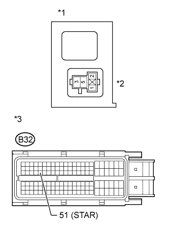
| 11.CHECK HARNESS AND CONNECTOR (ST CUT RELAY - ECM) |
Disconnect the ECM connector.
Remove the ST CUT relay from the No. 7 relay block.
Measure the resistance according to the value(s) in the table below.
- Standard Resistance (Check for Open):
Tester Connection
| Condition
| Specified Condition
|
ST CUT relay terminal 3 - B32-51 (STAR)
| Always
| Below 1 Ω
|
- Standard Resistance (Check for Short):
Tester Connection
| Condition
| Specified Condition
|
ST CUT relay terminal 3 or B32-51 (STAR) - Body ground
| Always
| 10 kΩ or higher
|
Text in Illustration*1
| No. 7 Relay Block
|
*2
| ST CUT
|
*3
| Front view of wire harness connector
(to ECM)
|
Reconnect the ECM connector.
Reinstall the ST CUT relay.
| | REPAIR OR REPLACE HARNESS OR CONNECTOR (ST CUT RELAY - ECM) |
|
|
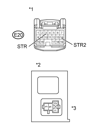
| 12.CHECK HARNESS AND CONNECTOR (ST CUT RELAY - MAIN BODY ECU) |
Disconnect the main body ECU connector.
Remove the ST CUT relay from the No. 7 relay block.
Measure the resistance according to the value(s) in the table below.
- Standard Resistance (Check for Open):
Tester Connection
| Condition
| Specified Condition
|
ST CUT relay terminal 3 - E20-14 (STR2)
| Always
| Below 1 Ω
|
ST CUT relay terminal 5 - E20-3 (STR)
| Always
| Below 1 Ω
|
- Standard Resistance (Check for Short):
Tester Connection
| Condition
| Specified Condition
|
ST CUT relay terminal 3 or E20-14 (STR2) - Body ground
| Always
| 10 kΩ or higher
|
ST CUT relay terminal 5 or E20-3 (STR) - Body ground
| Always
| 10 kΩ or higher
|
Text in Illustration*1
| Front view of wire harness connector
(to Main Body ECU)
|
*2
| No. 7 Relay Block
|
*3
| ST CUT
|
Reconnect the main body ECU connector.
Reinstall the ST CUT relay.
ResultResult
| Proceed to
|
OK (for Manual Transaxle)
| A
|
OK (for CVT)
| B
|
NG
| C
|
| |
|
| | REPAIR OR REPLACE HARNESS OR CONNECTOR (ST CUT RELAY - MAIN BODY ECU) |
|
|
| 13.CHECK HARNESS AND CONNECTOR (MAIN BODY ECU - CLUTCH START SWITCH ASSEMBLY) |
Disconnect the main body ECU connector.
Disconnect the clutch start switch assembly connector.
Measure the resistance according to the value(s) in the table below.
- Standard Resistance (Check for Open):
Tester Connection
| Condition
| Specified Condition
|
E20-3 (STR) - A4-2
| Always
| Below 1 Ω
|
- Standard Resistance (Check for Short):
Tester Connection
| Condition
| Specified Condition
|
E20-3 (STR) or A4-2 - Body ground
| Always
| 10 kΩ or higher
|
Text in Illustration*1
| Front view of wire harness connector
(to Main Body ECU)
|
*2
| Front view of wire harness connector
(to Clutch Start Switch Assembly)
|
Reconnect the main body ECU connector.
Reconnect the clutch start switch assembly connector.
| | REPAIR OR REPLACE HARNESS OR CONNECTOR (MAIN BODY ECU - CLUTCH START SWITCH ASSEMBLY) |
|
|
| 14.CHECK HARNESS AND CONNECTOR (MAIN BODY ECU - PARK/NEUTRAL POSITION SWITCH) |
Disconnect the main body ECU connector.
Disconnect the park/neutral position switch connector.
Measure the resistance according to the value(s) in the table below.
- Standard Resistance (Check for Open):
Tester Connection
| Condition
| Specified Condition
|
E20-3 (STR) - B28-4
| Always
| Below 1 Ω
|
- Standard Resistance (Check for Short):
Tester Connection
| Condition
| Specified Condition
|
E20-3 (STR) or B28-4 - Body ground
| Always
| 10 kΩ or higher
|
Text in Illustration*1
| Front view of wire harness connector
(to Main Body ECU)
|
*2
| Front view of wire harness connector
(to Park/Neutral Position Switch)
|
Reconnect the main body ECU connector.
Reconnect the park/neutral position switch connector.
| | REPAIR OR REPLACE HARNESS OR CONNECTOR (MAIN BODY ECU - PARK/NEUTRAL POSITION SWITCH) |
|
|
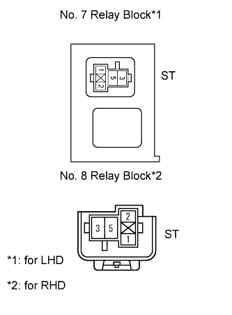
| 15.CHECK ST RELAY (INPUT VOLTAGE) |
Remove the ST relay from the No. 7 relay block (for LHD).
Remove the ST relay from the No. 8 relay block (for RHD).
Measure the voltage according to the value(s) in the table below.
- Standard Voltage:
Tester Connection
| Condition
| Specified Condition
|
ST relay terminal 1 - Body ground
| Engine cranking
| 11 to 14 V
|
- HINT:
- The engine does not crank because the terminal is not connected.
Reinstall the ST relay.
| | REPAIR OR REPLACE HARNESS OR CONNECTOR (ECM - ST RELAY) |
|
|
Remove the ST relay from the No. 7 relay block (for LHD).
Remove the ST relay from the No. 8 relay block (for RHD).
Measure the resistance according to the value(s) in the table below.
- Standard Resistance:
Tester Connection
| Condition
| Specified Condition
|
3 - 5
| Battery voltage not applied to terminal 1 and 2
| 10 kΩ or higher
|
3 - 5
| Battery voltage applied to terminal 1 and 2
| Below 1 Ω
|
Reinstall the ST relay.
| 17.CHECK HARNESS AND CONNECTOR (ST RELAY - BODY GROUND) |
Remove the ST relay from the No. 7 relay block (for LHD).
Remove the ST relay from the No. 8 relay block (for RHD).
Measure the resistance according to the value(s) in the table below.
- Standard Resistance:
Tester Connection
| Condition
| Specified Condition
|
ST relay terminal 2 - Body ground
| Always
| Below 1 Ω
|
Reinstall the ST relay.
| | REPAIR OR REPLACE HARNESS OR CONNECTOR (ST RELAY - BODY GROUND) |
|
|
| 18.CHECK ST RELAY (INPUT VOLTAGE) |
Remove the ST relay from the No. 7 relay block (for LHD).
Remove the ST relay from the No. 8 relay block (for RHD).
Measure the voltage according to the value(s) in the table below.
- Standard Voltage:
Tester Connection
| Switch Condition
| Specified Condition
|
ST relay terminal 5 - Body ground
| Ignition switch ON
| 11 to 14 V
|
Reinstall the ST relay.
| | REPAIR OR REPLACE HARNESS OR CONNECTOR (BATTERY - ST RELAY) |
|
|
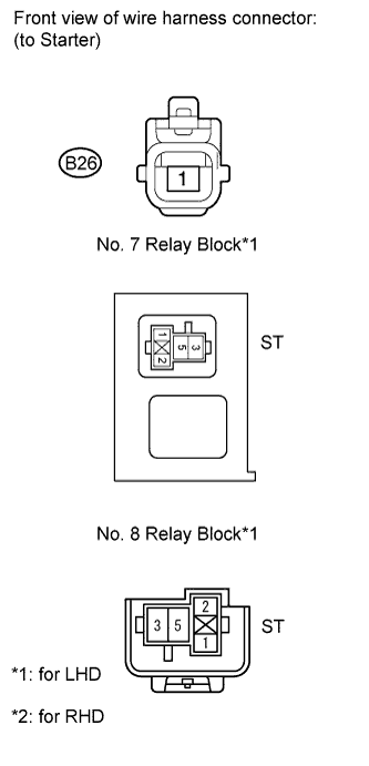
| 19.CHECK HARNESS AND CONNECTOR (ST RELAY - STARTER) |
Remove the ST relay from the No. 7 relay block (for LHD).
Remove the ST relay from the No. 8 relay block (for RHD).
Disconnect the starter connector.
Measure the resistance according to the value(s) in the table below.
- Standard Resistance (Check for Open):
Tester Connection
| Condition
| Specified Condition
|
ST relay terminal 3 - B26-1
| Always
| Below 1 Ω
|
- Standard Resistance (Check for Short):
Tester Connection
| Condition
| Specified Condition
|
ST relay terminal 3 or B26-1 - Body ground
| Always
| 10 kΩ or higher
|
Reinstall the ST relay.
Reconnect the starter connector.
| | REPAIR OR REPLACE HARNESS OR CONNECTOR (ST RELAY - STARTER) |
|
|
Inspect the starter (RAV4_ACA30 RM000001ETI01FX.html).
| OK |
|
|
|
| REPAIR OR REPLACE HARNESS OR CONNECTOR (BATTERY - STARTER) |
|