DISCONNECT COMPRESSOR WITH PULLEY ASSEMBLY (w/ Air Conditioning System)
DISCONNECT TRANSMISSION CONTROL CABLE ASSEMBLY (for Manual Transaxle)
REMOVE PROPELLER WITH CENTER BEARING SHAFT ASSEMBLY (for 4WD)
REMOVE DRIVE PLATE AND TORQUE CONVERTER SETTING BOLT (for CVT)
REMOVE CLUTCH RELEASE CYLINDER TO ACCUMULATOR TUBE (for Manual Transaxle)
REMOVE CLUTCH RELEASE BLEEDER SUB-ASSEMBLY (for Manual Transaxle)
REMOVE CLUTCH RELEASE WITH BEARING CYLINDER ASSEMBLY (for Manual Transaxle)
Engine Assembly -- Removal |
- NOTICE:
- for Manual Transaxle:
- When the transaxle is removed, be sure to use a new clutch release with bearing cylinder and new installation bolts. Removal of the transaxle allows the compressed clutch release with bearing cylinder to return to its original position, and dust could damage the seal of the clutch release with bearing cylinder, possibly causing clutch fluid leaks.
| 1. DISCHARGE FUEL SYSTEM PRESSURE |
Discharge fuel system pressure (RAV4_ACA30 RM000001EEY01OX.html).
| 2. DISCONNECT CABLE FROM NEGATIVE BATTERY TERMINAL |
- NOTICE:
- w/ Navigation System (for HDD):
After the ignition switch is turned off, the HDD navigation system requires approximately a minute to record various types of memory and settings. As a result, after turning the ignition switch off, wait a minute or more before disconnecting the cable from the negative (-) battery terminal. - Wait at least 90 seconds after disconnecting the cable from the negative (-) battery terminal to disable the SRS system.
| 3. POSITION FRONT WHEELS FACING STRAIGHT AHEAD |
| 4. REMOVE FRONT WHEEL |
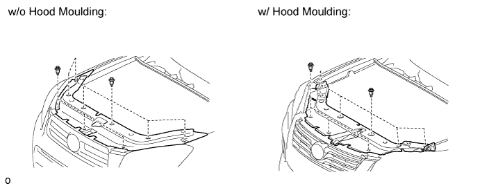
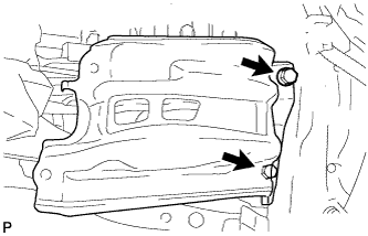
| 5. REMOVE RADIATOR SUPPORT OPENING COVER |
Remove the 9 clips and radiator support opening cover.
| 6. REMOVE NO. 1 ENGINE UNDER COVER |
Remove the 6 screws, 10 clips and under cover.
 |
| 7. REMOVE REAR ENGINE UNDER COVER RH |
Remove the 3 clips and under cover.
 |
| 8. REMOVE REAR ENGINE UNDER COVER LH |
Remove the 2 clips and under cover.
 |
| 9. REMOVE NO. 2 ENGINE UNDER COVER |
Remove the 3 clips and under cover.
 |
| 10. REMOVE FRONT FLOOR COVER |
Remove the nut, bolt, 3 clips and floor cover.
 |
| 11. DRAIN ENGINE COOLANT |
Install a vinyl hose to the drain cock plug on the radiator side.
 |
Loosen the radiator drain cock plug.
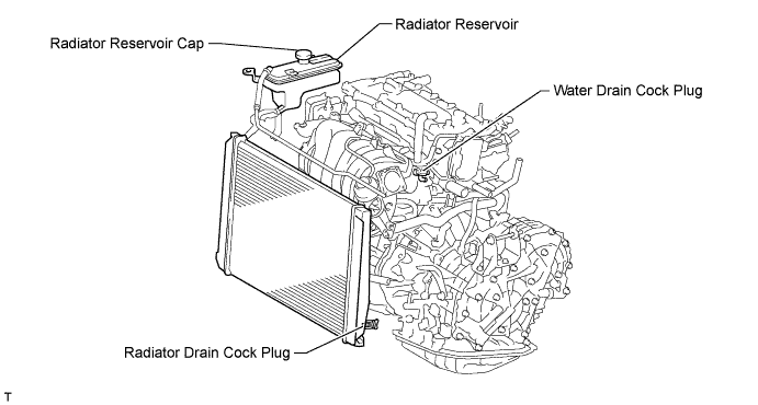
- HINT:
- Collect the coolant in a container and dispose of it according to the regulations in your area.
Remove the radiator reservoir cap.
- CAUTION:
- Do not remove the radiator reservoir cap while the engine and radiator are still hot. Pressurized, hot engine coolant and steam may be released and cause serious burns.
Loosen the water drain cock plug.
| 12. DRAIN ENGINE OIL |
Remove the oil filler cap.
Remove the 2 clips and open the oil pan drain service cover.
Remove the oil pan drain plug and gasket, and drain the engine oil into a container.
| 13. DRAIN MANUAL TRANSAXLE OIL (for Manual Transaxle) |
Remove the filler plug and gasket.
Text in Illustration *1 Filler Plug *2 Drain Plug
 |
Remove the drain plug and gasket to drain the manual transaxle oil.
Install a new gasket and the drain plug.
- Torque:
- 39 N*m{400 kgf*cm, 29 ft.*lbf}
| 14. DRAIN CONTINUOUSLY VARIABLE TRANSAXLE FLUID (for CVT) |
Using a 6 mm socket hexagon wrench, remove the overflow plug and gasket from the continuously variable transaxle assembly.
 |
Using a 6 mm socket hexagon wrench, remove the No. 1 transmission oil filler tube from the continuously variable transaxle assembly and drain the continuously variable transaxle fluid.
Text in Illustration *1 No. 1 Transmission Oil Filler Tube
 |
Using a 6 mm socket hexagon wrench, install the No. 1 transmission oil filler tube to the continuously variable transaxle assembly.
- Torque:
- 1.7 N*m{17 kgf*cm, 15 in.*lbf}
Temporarily install the gasket and overflow plug.
- HINT:
- Reuse the old gasket. The plug will be removed again to adjust the fluid level.
| 15. DRAIN TRANSFER OIL (for 4WD) |
Remove the drain plug and gasket, and drain the oil.
Install a new gasket and the drain plug.
- Torque:
- 39 N*m{398 kgf*cm, 28 ft.*lbf}
| 16. REMOVE NO. 2 CYLINDER HEAD COVER |
Hold the rear of the cover and raise it to detach the 2 clips on the rear of the cover. Continue to raise the cover to detach the 2 clips on the front of the cover and remove the cover.
- NOTICE:
- Attempting to detach both front and rear clips at the same time may cause the cover to break.
 |
| 17. REMOVE RADIATOR RESERVOIR ASSEMBLY |
Disconnect the No. 1 and No. 2 water by-pass hoses.
 |
Remove the 2 bolts and radiator reservoir.
| 18. REMOVE V-RIBBED BELT |
Loosen bolts A and B.
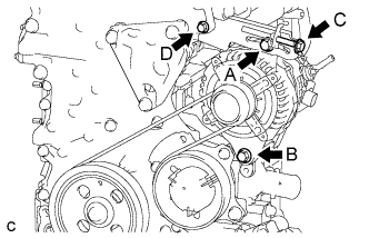 |
Loosen bolt C and remove the V-ribbed belt.
- NOTICE:
- Do not loosen bolt D.
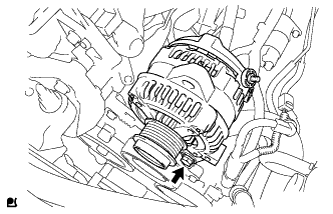
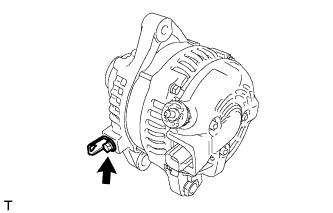
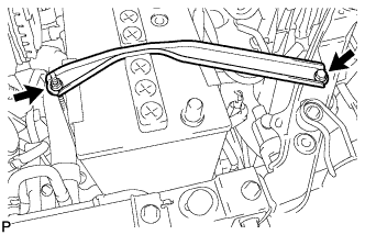
| 19. REMOVE GENERATOR ASSEMBLY |
Remove the terminal cap.
 |
Remove the nut and disconnect the wire harness from terminal B.
Disconnect the connector and wire harness clamp.
Loosen the 3 bolts.
 |
Remove the 2 bolts and adjusting bar.
 |
Remove the bolt and generator.
 |
Remove the bolt and wire harness clamp bracket.
 |
| 20. DISCONNECT NO. 2 RADIATOR HOSE |
Disconnect the radiator hose from the water inlet.
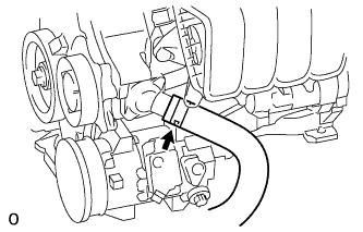 |
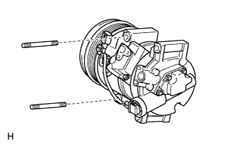
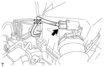
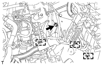
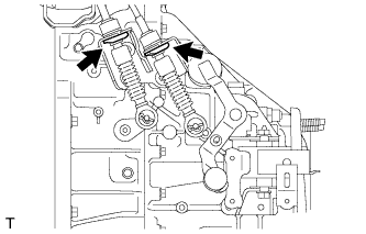
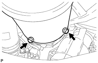
| 21. DISCONNECT COMPRESSOR WITH PULLEY ASSEMBLY (w/ Air Conditioning System) |
Disconnect the connector.
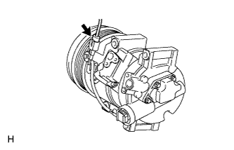 |
Remove the 2 bolts and 2 nuts.
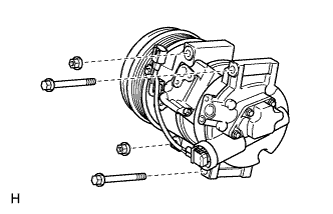 |
Using an E8 "TORX" socket wrench, remove the 2 stud bolts and disconnect the compressor with pulley assembly.
- HINT:
- It is not necessary to completely remove the compressor. With the hoses connected to the compressor, hang the compressor on the vehicle body with a rope.
 |
| 22. REMOVE BATTERY CLAMP SUB-ASSEMBLY |
Remove the bolt and loosen the nut.
 |
Detach the hook of the battery clamp from the front battery bracket, and then remove the battery clamp.
| 23. REMOVE BATTERY |
| 24. REMOVE BATTERY TRAY |
| 25. REMOVE FRONT BATTERY BRACKET |
Detach the 3 wire harness clamps.
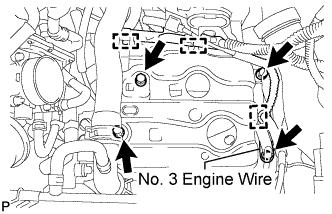 |
Remove the 4 bolts, disconnect the No. 3 engine wire and remove the front battery bracket.
| 26. REMOVE BATTERY BRACKET REINFORCEMENT |
Remove the 2 bolts and battery bracket reinforcement.
 |
| 27. REMOVE AIR CLEANER CAP SUB-ASSEMBLY |
Disconnect the mass air flow meter connector.
 |
Detach the clamp.
Disconnect the No. 2 ventilation hose from the cylinder head cover.
 |
Squeeze the taps of the air cleaner hose clamp, and then disconnect the air cleaner hose from the throttle body.
Detach the 2 hook clamps, and then remove the air cleaner cap and hose.
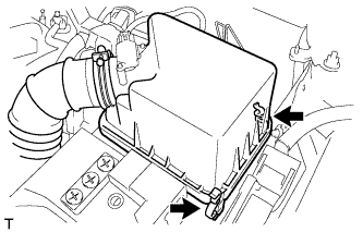 |
| 28. REMOVE AIR CLEANER CASE |
Disconnect the wire harness clamp from the air cleaner case.
 |
Remove the 3 bolts and air cleaner case.
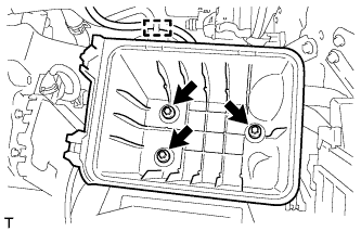
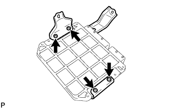
| 29. REMOVE ECM |
Remove the 3 bolts of the ECM with brackets.
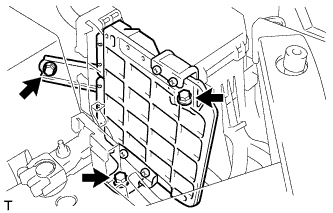 |
Disconnect the 2 ECM connectors.
- NOTICE:
- After disconnecting the connector, make sure that dirt, water and other foreign matter does not contact the connecting part of the connector.
Raise the 2 levers while pushing the locks on the 2 levers, and disconnect the 2 ECM connectors.
 |
Remove the ECM with brackets.
Remove the 4 screws and 2 ECM brackets.
 |
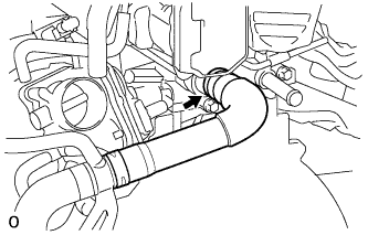
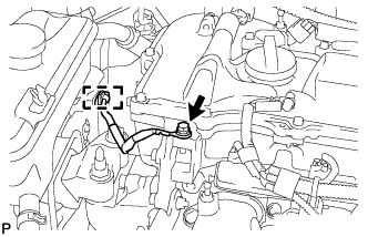
| 30. DISCONNECT NO. 1 RADIATOR HOSE |
Disconnect the radiator hose from the cylinder head.
 |
| 31. DISCONNECT FUEL TUBE SUB-ASSEMBLY |
Remove the No. 1 fuel pipe clamp.
 |
Pinch the tube connector and then pull the fuel tube connector off of the fuel pipe.
- NOTICE:
- Check for foreign matter in the fuel tube around the fuel tube connector. Clean it if necessary. Foreign matter can affect the ability of the O-ring to seal the connector and fuel main tube.
- Do not use any tools to separate the connector and pipe.
- Do not forcefully bend, kink or twist the hose.
- Keep the connector and pipe free from foreign matter.
- If the connector and pipe are stuck together, pinch the connector and turn it carefully to disconnect it.
- Put the connector in a plastic bag to prevent damage and contamination.
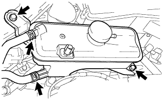
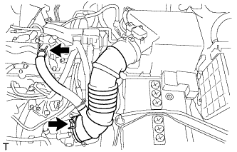
| 32. DISCONNECT WIRE HARNESS AND HOSE |
Remove the bolt. Then disconnect the 3 clamps and engine wire.
 |
Remove the nut and disconnect the engine wire.
 |
Disconnect the 3 relay block connectors.
Remove the bolt. Then disconnect the clamp and ground wire.
 |
Disconnect the connector tube hose.
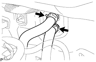
 |
Disconnect the 2 heater hoses.
 |
| 33. DISCONNECT TRANSMISSION CONTROL CABLE ASSEMBLY (for Manual Transaxle) |
Removal the 2 clips and washers, and disconnect the top ends of the control cable from the transaxle.
 |
Remove the 2 clips and disconnect the control cable from the control cable bracket.
 |
| 34. DISCONNECT TRANSMISSION CONTROL CABLE ASSEMBLY (for CVT) |
Remove the nut and disconnect the control cable from the control shaft lever.
 |
Remove the clip and disconnect the transmission control cable from the control cable bracket.
Disconnect the control cable from the control cable support.
 |
Remove the bolt and disconnect the clamp of the control cable.
 |
| 35. DISCONNECT CLUTCH TUBE (for Manual Transaxle) |
Using a 10 mm union nut wrench, disconnect the clutch hose from the flexible hose tube.
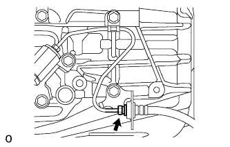 |
Remove the clip and disconnect the clutch hose.
| 36. REMOVE COLUMN HOLE COVER SILENCER SHEET |
Turn back the floor carpet and remove the 2 clips and silencer sheet.
 |
| 37. DISCONNECT NO. 2 STEERING INTERMEDIATE SHAFT ASSEMBLY |
Use a seat belt to fix the steering wheel in place to avoid breakage of the spiral cable.
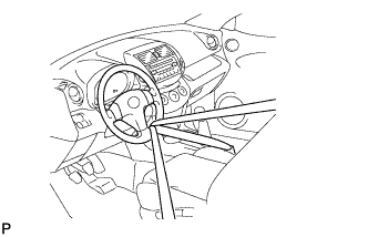 |
Place matchmarks on the No. 2 steering intermediate shaft and steering intermediate shaft.
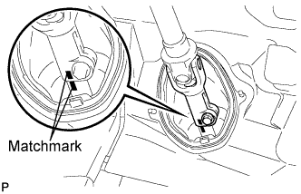 |
Remove the bolt and disconnect the No. 2 steering intermediate shaft.
| 38. DISCONNECT NO. 1 STEERING COLUMN HOLE COVER SUB-ASSEMBLY |
Remove the clip A, detach the clip B from the body and disconnect the No. 1 steering column hole cover.
- NOTICE:
- Do not damage clips A and B.
 |
| 39. REMOVE FRONT AXLE SHAFT NUT LH |
Using SST and a hammer, unstake the staked part of the nut.
- SST
- 09930-00010
- NOTICE:
- Loosen the staked part of the nut completely, otherwise the screw of the drive shaft may be damaged.
 |
While applying the brakes, remove the lock axle hub nut.
| 40. REMOVE FRONT AXLE SHAFT NUT RH |
- HINT:
- Perform the same procedures described for the LH side.
| 41. REMOVE FRONT AXLE HUB SUB-ASSEMBLY LH |
Remove the front axle hub sub-assembly LH (RAV4_ACA30 RM00000227J00IX.html).
| 42. REMOVE FRONT AXLE HUB SUB-ASSEMBLY RH |
- HINT:
- Perform the same procedures described for the LH side.
| 43. REMOVE DRIVE SHAFT |
for 2WD:
Remove the front drive shafts (RAV4_ACA30 RM00000226L014X_01_0019.html).
for 4WD:
Remove the front drive shafts (RAV4_ACA30 RM00000226Q008X_02_0019.html).
| 44. REMOVE FRONT EXHAUST PIPE ASSEMBLY |
Remove the 2 bolts and disconnect the front exhaust pipe from the center exhaust pipe.
 |
Remove the gasket from the exhaust pipe.
Remove the 2 bolts, 2 compression springs and front exhaust pipe.
 |
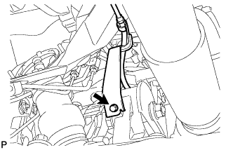
| 45. DISCONNECT HEATED OXYGEN SENSOR (for 4WD) |
Disconnect the grommet from the floor panel.
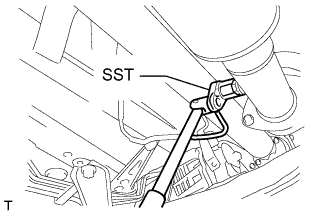 |
Using SST, loosen the sensor, and then disconnect the sensor by hand.
- SST
- 09224-00010
- HINT:
- Rotate the sensor counterclockwise to disconnect it from the front exhaust pipe, and record how many times it is rotated.
- NOTICE:
- Do not strike the metal part of the sensor.
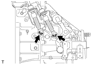
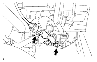
| 46. REMOVE PROPELLER WITH CENTER BEARING SHAFT ASSEMBLY (for 4WD) |
Remove the 2 bolts and 2 adjusting washers, and disconnect the propeller with center bearing shaft.
- NOTICE:
- During the removal, do not exert excessive force on the universal joint.
- When removing, transporting or storing the propeller with center bearing shaft assembly, do not allow the No. 2 joint angle to exceed 20°.
 |
Place matchmarks on the differential carrier and propeller shaft.
 |
Remove the 4 nuts and 4 washers, and disconnect the propeller shaft and differential carrier.
Place matchmarks on the transfer and propeller shaft.
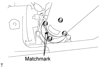 |
Remove the 4 nuts and 4 washers, and disconnect the propeller shaft from the transfer.
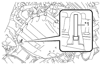
| 47. REMOVE DRIVE PLATE AND TORQUE CONVERTER SETTING BOLT (for CVT) |
 |
Remove the flywheel housing under cover.
Turn the crankshaft to gain access to the 6 bolts and remove each bolt while holding the crankshaft pulley bolt with a wrench.
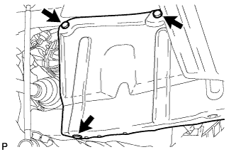
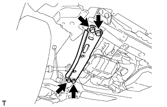
| 48. REMOVE FRONT SUSPENSION MEMBER REINFORCEMENT LH |
Remove the 4 bolts and reinforcement.
 |
| 49. REMOVE FRONT SUSPENSION MEMBER REINFORCEMENT RH |
Remove the 4 bolts and reinforcement.
 |
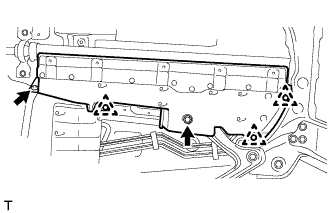
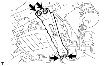
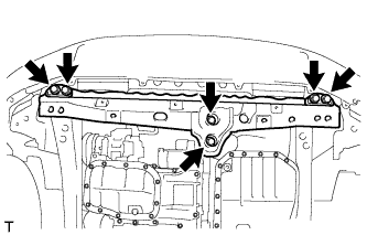
| 50. REMOVE FRONT CROSSMEMBER SUB-ASSEMBLY |
Remove the 6 bolts and crossmember.
 |
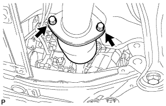
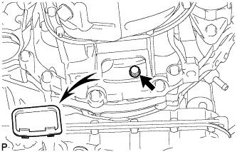
| 51. REMOVE FRONT ENGINE MOUNTING INSULATOR |
Remove the bolt, nut and engine mounting insulator.
 |
| 52. REMOVE ENGINE AND TRANSAXLE |
Set an engine lifter underneath the engine.
- HINT:
- Place the engine on wooden blocks or equivalent so that the engine is level.
Remove the bolt and 2 nuts, and disconnect the engine mounting insulator RH.
 |
Remove the bolt and nut, and disconnect the engine mounting insulator LH.
 |
Remove the 6 bolts and front suspension member brace rear RH and LH.
 |
Remove the 2 bolts and front suspension crossmember.
Operate the engine lifter and slowly remove the engine from the vehicle.
- NOTICE:
- Make sure that the engine is clear of all wiring and hoses.
- While lowering the engine from the vehicle, do not allow it to contact the vehicle.
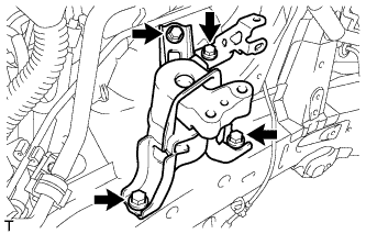
| 53. INSTALL ENGINE HANGER |
Disconnect the air fuel ratio sensor connector and remove the bolt and air fuel ratio sensor bracket.
 |
Install the No. 1 and No. 2 engine hangers with 2 bolts as shown in the illustration.
- Torque:
- 43 N*m{438 kgf*cm, 32 ft.*lbf}
Text in Illustration *1 No. 1 Engine Hanger *2 No. 2 Engine Hanger - HINT:
No. 1 Engine Hanger 12281-37021 No. 2 Engine Hanger 12282-37011 Bolt 91552-81050
 |
Attach an engine sling device and hang the engine with a chain block.
| 54. REMOVE STEERING GEAR HEAT INSULATOR (for RHD) |
Remove the bolt and heat insulator from the steering gear.
| 55. REMOVE NO. 1 STEERING COLUMN HOLE COVER SUB-ASSEMBLY |
Remove the clamp and disconnect the steering column hole cover from the steering gear.
| 56. REMOVE FRONT SUSPENSION CROSSMEMBER SUB-ASSEMBLY |
Remove the bolt and front suspension crossmember from the engine.
 |
| 57. REMOVE STARTER ASSEMBLY |
Disconnect the terminal cap.
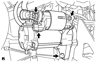 |
Remove the nut and disconnect the starter wire.
Disconnect the connector.
Remove the 2 bolts and starter.
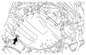
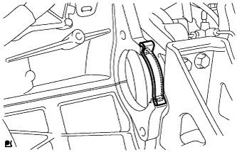
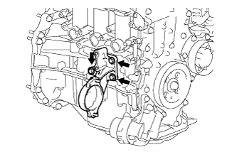
| 58. REMOVE FLYWHEEL HOUSING SIDE COVER |
Remove the flywheel housing side cover from the cylinder block.
 |
| 59. REMOVE CONTINUOUSLY VARIABLE TRANSAXLE ASSEMBLY (for CVT) |
Remove the continuously variable transaxle assembly (RAV4_ACA30 RM00000192D01ZX.html).
| 60. REMOVE MANUAL TRANSAXLE ASSEMBLY (for Manual Transaxle) |
for 2WD:
Remove the manual transaxle assembly (RAV4_ACA30 RM000001B3W02LX.html).
for 4WD:
Remove the manual transaxle assembly (RAV4_ACA30 RM000001B3W02WX.html).
| 61. REMOVE DRIVE PLATE AND RING GEAR SUB-ASSEMBLY (for CVT) |
Using SST, hold the crankshaft.
- SST
- 09330-00021
09213-58014(91551-80840)
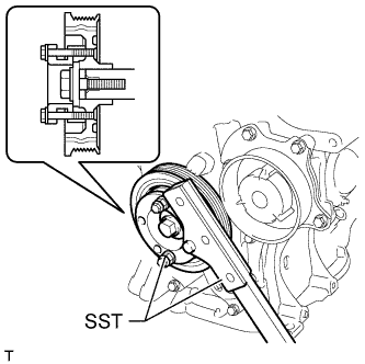 |
Remove the 8 bolts, rear spacer, drive plate and front spacer.
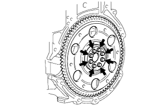 |
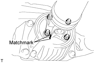
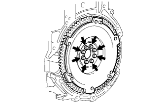
| 62. REMOVE CLUTCH COVER ASSEMBLY (for Manual Transaxle) |
 |
Put matchmarks on the clutch cover assembly and flywheel sub-assembly.
Text in Illustration *1 Matchmark
Loosen each set bolt one turn at a time in the order shown in the illustration until the spring tension is released.
Remove the set bolts and pull off the clutch cover assembly.
- NOTICE:
- Do not drop the clutch disc assembly.
| 63. REMOVE CLUTCH DISC ASSEMBLY (for Manual Transaxle) |
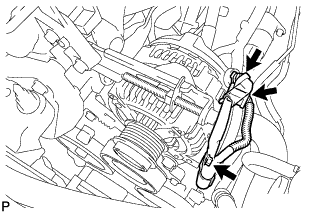
| 64. REMOVE ORIFICE TO FLEXIBLE HOSE TUBE (for Manual Transaxle) |
 |
Using a union nut wrench, separate the orifice to flexible hose tube from the clutch orifice assembly.
Remove the bolt and orifice to flexible hose tube.
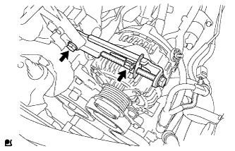
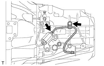
| 65. REMOVE CLUTCH RELEASE CYLINDER TO ACCUMULATOR TUBE (for Manual Transaxle) |
 |
Using a union nut wrench, remove the clutch release cylinder to accumulator tube.
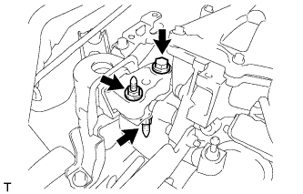
| 66. REMOVE CLUTCH ORIFICE ASSEMBLY (for Manual Transaxle) |
 |
Remove the 2 bolts and clutch orifice assembly.
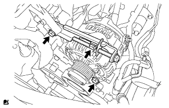
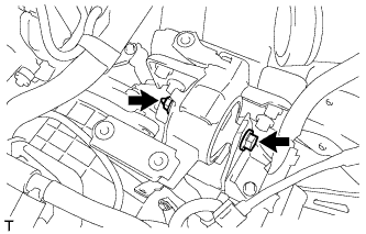
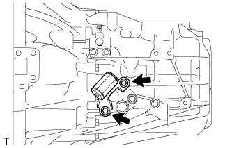
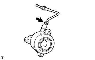
| 67. REMOVE CLUTCH RELEASE BLEEDER SUB-ASSEMBLY (for Manual Transaxle) |
 |
Using a union nut wrench, separate the clutch release bleeder sub-assembly from the clutch release cylinder to bleeder tube.
Remove the 2 bolts and clutch release bleeder sub-assembly from the manual transaxle assembly.
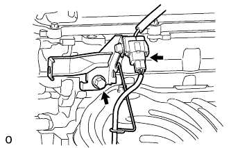
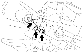
| 68. REMOVE CLUTCH RELEASE WITH BEARING CYLINDER ASSEMBLY (for Manual Transaxle) |
Remove the clutch tube boot from the manual transaxle assembly.
 |
Remove the 3 bolts and clutch release with bearing cylinder assembly and clutch release cylinder to bleeder tube.
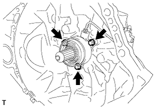 |
Using a union nut wrench, remove the clutch release cylinder to bleeder tube from the clutch release with bearing cylinder assembly.
 |
| 69. REMOVE FLYWHEEL SUB-ASSEMBLY (for Manual Transaxle) |
Using SST, hold the crankshaft.
- SST
- 09330-00021
09213-58014(91551-80840)
|
Remove the 8 bolts and flywheel.
 |
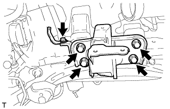
| 70. INSTALL ENGINE ON ENGINE STAND |
Install the engine onto an engine stand with the bolts.
Remove the 2 bolts, and 2 engine hangers.
| 71. REMOVE ENGINE WIRE |
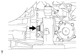
Remove the engine wire from the engine.
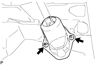
| 72. REMOVE DRIVE SHAFT BEARING BRACKET |
Remove the 3 bolts and bearing bracket.
 |
| 73. REMOVE REAR ENGINE MOUNTING INSULATOR |
- HINT:
 |
- Perform this procedure only when replacement of the engine mounting insulator is necessary.
Remove the 2 bolts, 2 nuts and engine mounting insulator.
| 74. REMOVE ENGINE MOUNTING INSULATOR SUB-ASSEMBLY RH |
- HINT:
 |
- Perform this procedure only when replacement of the engine mounting insulator is necessary.
Remove the bolt and radiator reservoir bracket.
Remove the 3 bolts and engine mounting insulator.
| 75. REMOVE ENGINE MOUNTING INSULATOR LH |
- HINT:
 |
- Perform this procedure only when replacement of the engine mounting insulator is necessary.
Remove the bolt and wire harness clamp bracket.
Remove the 4 bolts and engine mounting insulator.