Engine. Toyota Rav4. Aca30, 33, 38 Gsa33 Zsa30, 35
DESCRIPTION
WIRING DIAGRAM
INSPECTION PROCEDURE
PERFORM ACTIVE TEST USING INTELLIGENT TESTER (FUEL PUMP/SPD)
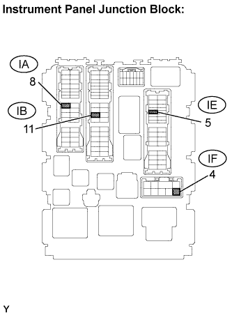
INSPECT INSTRUMENT PANEL JUNCTION BLOCK ASSEMBLY (C/OPN RELAY INPUT VOLTAGE)
CHECK WIRE HARNESS (INSTRUMENT PANEL JUNCTION BLOCK - INTEGRATION RELAY AND IG2 RELAY)
INSPECT INSTRUMENT PANEL JUNCTION BLOCK ASSEMBLY (C/OPN RELAY)
CHECK WIRE HARNESS (INSTRUMENT PANEL JUNCTION BLOCK - ECM)
PERFORM ACTIVE TEST USING INTELLIGENT TESTER
INSPECT F/PMP RELAY
CHECK WIRE HARNESS (F/PMP RELAY - ECM AND INSTRUMENT PANEL JUNCTION BLOCK)
CHECK WIRE HARNESS (F/PMP - FUEL PUMP AND PUMP RESISTOR)
INSPECT FUEL PUMP
INSPECT FUEL PUMP RESISTOR
READ VALUE USING INTELLIGENT TESTER (STARTER SIG)
READ VALUE USING INTELLIGENT TESTER (ENGINE SPD)
SFI SYSTEM - Fuel Pump Control Circuit |
DESCRIPTION
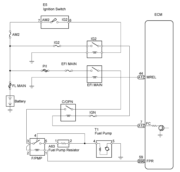
The F/PMP relay switches the fuel pump speed according to the engine conditions. The fuel pump operates when the ECM receives the starter-operating signal (STA) and crankshaft-rotating signal (NE). The F/PMP relay is turned ON while the engine is idling or operating at low load. This causes current to flow through the fuel pump resistor to the fuel pump. The fuel pump then operates at low speed. The F/PMP relay is turned OFF while the engine is cranking or operating at high load. The fuel pump then operates at normal speed.
WIRING DIAGRAM
INSPECTION PROCEDURE
| 1.PERFORM ACTIVE TEST USING INTELLIGENT TESTER (FUEL PUMP/SPD) |
Connect the intelligent tester to the DLC3.
Turn the ignition switch to the ON position and turn the tester on.
Select the following menu items: Powertrain / Engine and ECT / Active Test / Control the Fuel Pump / Speed.
Check whether the fuel pump operating sound occurs when performing the Active Test on the tester.
- OK:
- Fuel pump operating sound occurs.
| 2.INSPECT INSTRUMENT PANEL JUNCTION BLOCK ASSEMBLY (C/OPN RELAY INPUT VOLTAGE) |
Measure the voltage between the terminal of the instrument panel junction block and the body ground when the ignition switch is turned ON and OFF.
- Standard voltage:
Tester Connection
| Ignition Switch Condition
| Specified Condition
|
IB-11 - Body ground
| OFF
| Below 1 V
|
IF-4 - Body ground
|
IB-11 - Body ground
| ON
| 9 to 14 V
|
IF-4 - Body ground
|
| 3.CHECK WIRE HARNESS (INSTRUMENT PANEL JUNCTION BLOCK - INTEGRATION RELAY AND IG2 RELAY) |
Remove the integration relay and IG2 relay from the engine room No. 1 relay block.
Disconnect the instrument panel junction block connector.
Measure the resistance.
- Standard resistance:
Tester Connection
| Specified Condition
|
IG2 relay 5 - IF-4
| Below 1 Ω
|
1A-4 - IB-11
| Below 1 Ω
|
IF-4 - Body ground
| 10 kΩor higher
|
IB-11 - Body ground
| 10 kΩor higher
|
Reinstall the integration relay and IG2 relay.
Reconnect the instrument panel junction block connector.
| | REPAIR OR REPLACE HARNESS OR CONNECTOR |
|
|
| 4.INSPECT INSTRUMENT PANEL JUNCTION BLOCK ASSEMBLY (C/OPN RELAY) |
Remove the instrument panel junction block.
Measure the C/OPN relay resistance.
- Standard resistance:
Tester Connection
| Specified Condition
|
IB-11 - IA-8
| 10 kΩ or higher
|
Below 1 Ω
(When battery voltage is applied to terminals IF-4 and IE-5)
|
- HINT:
- Relay coil circuit between IF-4 and IE-5 is through IGN fuse.
Reinstall the instrument panel junction block.
| | REPLACE INSTRUMENT PANEL JUNCTION BLOCK ASSEMBLY |
|
|
| 5.CHECK WIRE HARNESS (INSTRUMENT PANEL JUNCTION BLOCK - ECM) |
Disconnect the ECM connector.
Disconnect the IE connector from the instrument panel junction block.
Measure the resistance.
- Standard resistance:
Tester Connection
| Specified Condition
|
IE-5 - A12-7 (FC)
| Below 1Ω
|
IE-5 or A12-7 (FC) - Body ground
| 10 kΩ or higher
|
Reconnect the instrument panel junction block and the ECM connectors.
| | REPAIR OR REPLACE HARNESS OR CONNECTOR |
|
|
| 6.PERFORM ACTIVE TEST USING INTELLIGENT TESTER |
Connect the intelligent tester to the DLC3.
Turn the ignition switch ON and turn the tester on.
Select the following menu items: Powertrain / Engine and ECT / Active Test / Control the Fuel Pump / Speed.
Check the operation of the relay while operating it using the intelligent tester.
- OK:
- Operating noise can be heard from the relay.
Inspect the F/PMP relay (RAV4_ACA30 RM000001GHH01GX.html).
| 8.CHECK WIRE HARNESS (F/PMP RELAY - ECM AND INSTRUMENT PANEL JUNCTION BLOCK) |
Remove the F/PMP relay from the engine room No. 1 relay block.
Disconnect the ECM connector.
Disconnect the IA instrument panel junction block connector.
Measure the resistance.
- Standard resistance:
Tester Connection
| Specified Condition
|
F/PMP relay terminal 1 - B96-59 (FPR)
| Below 1 Ω
|
F/PMP relay terminal 2 - IA-8
| Below 1 Ω
|
F/PMP relay terminal 3 - IA-8
| Below 1 Ω
|
F/PMP relay terminal 1 or B96-59 (FPR) - Body ground
| 10 kΩ or higher
|
F/PMP relay terminal 2 or IA-8 - Body ground
| 10 kΩ or higher
|
F/PMP relay terminal 3 or IA-8 - Body ground
| 10 kΩ or higher
|
Reconnect the ECM connector
Reconnect the instrument panel junction block connector.
Reinstall the F/PMP relay.
| | REPAIR OR REPLACE HARNESS OR CONNECTOR |
|
|
| 9.CHECK WIRE HARNESS (F/PMP - FUEL PUMP AND PUMP RESISTOR) |
Remove the F/PMP relay from the engine room No. 1 relay block.
Disconnect the fuel pump connector.
Disconnect the fuel pump resistor connector.
Measure the resistance.
- Standard resistance:
Tester Connection
| Specified Condition
|
F/PMP relay terminal 4 - T1-4
| Below 1 Ω
|
F/PMP relay terminal 5 - A63-1
| Below 1 Ω
|
A63-2 - T1-4
| Below 1 Ω
|
T1-5 - Body ground
| Below 1 Ω
|
F/PMP relay terminal 4 or T1-4 - Body ground
| 10 kΩ or higher
|
F/PMP relay terminal 5 or A63-1 - Body ground
| 10 kΩ or higher
|
A63-2 or T1-4 - Body ground
| 10 kΩ or higher
|
Reconnect the fuel pump resistor connector.
Reconnect the fuel pump connector.
Reinstall the F/PMP relay.
| | REPAIR OR REPLACE HARNESS OR CONNECTOR |
|
|
Inspect fuel pump resistance.
Measure the resistance between the terminals.
- Standard resistance:
- 0.2 to 3.0 Ω at 20°C (68°F)
Inspect fuel pump operation.
Apply the battery voltage to both the terminals. Check that the pump operates.
- NOTICE:
- These tests must be done quickly (within 10 seconds) to prevent the coil from burning out.
- Keep the fuel pump as far away from the battery as possible.
- Always turn the voltage on and off on the battery side, not the fuel pump side.
| 11.INSPECT FUEL PUMP RESISTOR |
Measure the resistance of the fuel pump resistor.
- Standard resistance:
- 0.30 to 0.34 Ω at 20°C (68°F)
| | REPLACE FUEL PUMP RESISTOR |
|
|
| 12.READ VALUE USING INTELLIGENT TESTER (STARTER SIG) |
Connect the intelligent tester to the DLC3.
Turn the ignition switch ON and turn the tester on.
Select the following menu items: Powertrain / Engine and ECT / Data List / Starter Signal.
Check the result when the ignition switch is turned ON and START.
- OK:
Ignition Switch Position
| STARTER SIG
|
ON
| OFF
|
START
| ON
|
| | REPAIR OR REPLACE STARTING SYSTEM |
|
|
| 13.READ VALUE USING INTELLIGENT TESTER (ENGINE SPD) |
Connect the intelligent tester to the DLC3.
Turn the ignition switch to the ON position and turn the tester on.
Select the following menu items: Powertrain / Engine and ECT / Data List / Engine Speed.
Read the values displayed on the tester while cranking.
- Standard:
- Values are displayed continuously.
| | REPAIR OR REPLACE CRANKSHAFT POSITION SENSOR CIRCUIT |
|
|