Engine. Toyota Rav4. Aca30, 33, 38 Gsa33 Zsa30, 35
DESCRIPTION
WIRING DIAGRAM
INSPECTION PROCEDURE
INSPECT FUSES (P/I, AM2, IG2, EFI MAIN AND IGN)
INSPECT RELAY (IG2, EFI MAIN)
CHECK WIRE HARNESS (ECM - BODY GROUND)
INSPECT ECM (IGSW VOLTAGE)
CHECK WIRE HARNESS (RELAY BLOCK, ECM, IGNITION SWITCH, BATTERY)
INSPECT IGNITION SWITCH
CHECK WIRE HARNESS (INTEGRATION RELAY - ECM, BATTERY AND BODY GROUND)
SFI SYSTEM - ECM Power Source Circuit |
DESCRIPTION
When the ignition switch is turned ON, the battery voltage is applied to the IGSW of the ECM. The output signal from the MREL terminal of the ECM causes a current to flow to the coil, closing the contacts of the integration relay (EFI MAIN relay) and supplying power to either terminal +B or +B2 of the ECM.
WIRING DIAGRAM
INSPECTION PROCEDURE
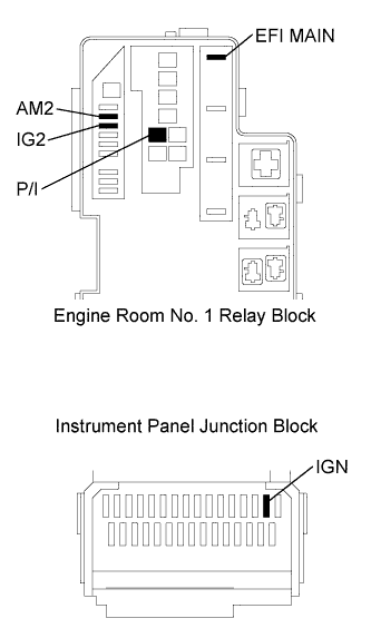
| 1.INSPECT FUSES (P/I, AM2, IG2, EFI MAIN AND IGN) |
Remove the P/I fuse, AM2 fuse, IG2 fuse and EFI MAIN fuse from the engine room No. 1 relay block.
Remove the IGN fuse from the instrument panel junction block.
Measure the resistance of the fuses.
- Standard resistance:
- Below 1 Ω
Reinstall the fuses.
| | CHECK FOR SHORT IN ALL HARNESSES AND CONNECTORS CONNECTED TO FUSE AND REPLACE FUSE |
|
|
| 2.INSPECT RELAY (IG2, EFI MAIN) |
Remove the integration relay and IG2 relay from the engine room No. 1 relay block.
Measure the resistance between the terminals of the integration relay.
- Standard resistance:
Tester Connection
| Specified Condition
|
1C-1 - 1A-4
| 10 kΩ or higher
|
Below 1 Ω
(When battery voltage is applied to terminals 1A-2 and 1A-3)
|
Measure the resistance between the terminals of the IG2 relay.
- Standard resistance:
Tester Connection
| Specified Condition
|
3 - 5
| 10 kΩ or higher
|
Below 1 Ω
(When battery voltage is applied to terminals 1 and 2)
|
Reinstall the IG2 relay.
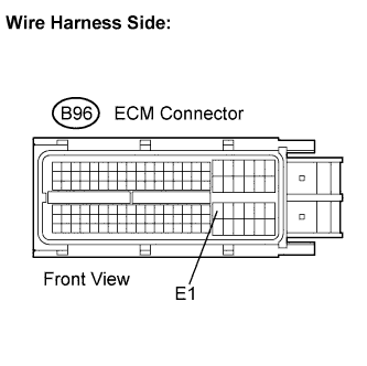
| 3.CHECK WIRE HARNESS (ECM - BODY GROUND) |
Disconnect the ECM connector.
Measure the resistance.
- Standard resistance:
Tester Connection
| Specified Condition
|
B96-81 (E1) - Body ground
| Below 1 Ω
|
Reconnect the ECM connector.
| | REPAIR OR REPLACE HARNESS OR CONNECTOR |
|
|
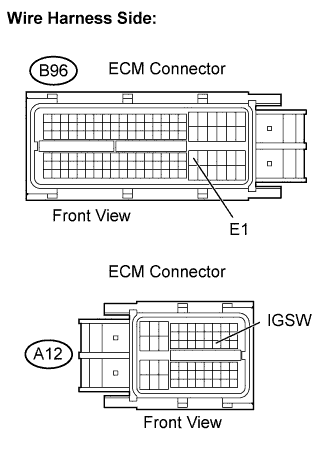
| 4.INSPECT ECM (IGSW VOLTAGE) |
Disconnect the ECM connectors.
Turn the ignition switch to the ON position.
Measure the voltage between the terminals of the ECM connectors.
- Standard voltage:
Tester Connection
| Specified Condition
|
A12-28 (IGSW) - B96-81 (E1)
| 9 to 14 V
|
Reconnect the ECM connector.
| 5.CHECK WIRE HARNESS (RELAY BLOCK, ECM, IGNITION SWITCH, BATTERY) |
Disconnect the ECM connector.
Disconnect the ignition switch connector.
Disconnect the cable from the battery positive terminal.
Remove the AM2 fuse and IG2 relay.
Measure the resistance between the terminals.
- Standard resistance:
Tester Connection
| Specified Condition
|
A12-28 (IGSW) - IG2 relay terminal 5
| Below 1 Ω
|
IG2 relay terminal 2 - Body ground
| Below 1 Ω
|
Positive (+) battery cable - IG2 relay terminal 3
| Below 1 Ω
|
Positive (+) battery cable - AM2 fuse terminal 1
| Below 1 Ω
|
E5-7 (AM2) - AM2 fuse terminal 2
| Below 1 Ω
|
E5-6 (IG2) - IG2 relay terminal 1
| Below 1 Ω
|
A12-28 (IGSW) or IG2 relay terminal 5 - Body ground
| 10 kΩ or higher
|
Positive (+) battery cable or AM2 fuse terminal 1 - Body ground
| 10 kΩ or higher
|
Positive (+) battery cable or IG2 relay terminal 3 - Body ground
| 10 kΩ or higher
|
E5-7 (AM2) or AM2 fuse terminal 2 - Body ground
| 10 kΩ or higher
|
E5-6 (IG2) or IG2 relay terminal 1 - Body ground
| 10 kΩ or higher
|
Reinstall the relay and fuse.
Reconnect the connectors.
| | REPAIR OR REPLACE HARNESS OR CONNECTOR |
|
|
| 6.INSPECT IGNITION SWITCH |
RAV4_ACA30 RM0000025HZ006X.html
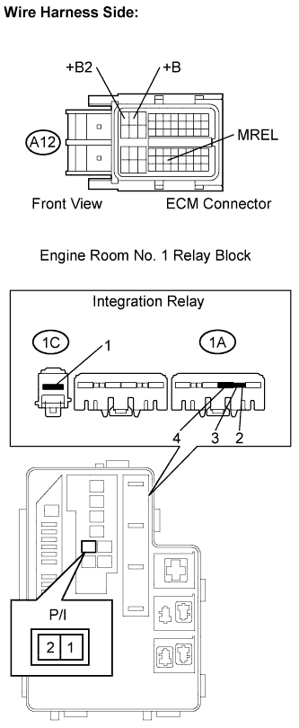
| 7.CHECK WIRE HARNESS (INTEGRATION RELAY - ECM, BATTERY AND BODY GROUND) |
Disconnect the ECM connector.
Disconnect the cable from the battery positive terminal.
Remove the integration relay from the engine room No. 1 relay block.
Disconnect the integration relay connector.
Remove the P/I fuse from the engine room No. 1 relay block.
Measure the resistance between the terminals.
- Standard resistance (Check for open):
Tester Connection
| Specified Condition
|
A12-2 (+B) - 1A-4
| Below 1 Ω
|
A12-1 (+B2) - 1A-4
| Below 1 Ω
|
A12-44 (MREL) - 1A-2
| Below 1 Ω
|
P/I fuse terminal 2 - 1C-1
| Below 1 Ω
|
P/I fuse terminal 1 - Positive (+) battery cable
| Below 1 Ω
|
1A-3 - Body ground
| Below 1 Ω
|
A12-2 (+B) or 1A-4 - Body ground
| 10 kΩ or higher
|
A12-1 (+B2) or 1A-4 - Body ground
| 10 kΩ or higher
|
A12-44 (MREL) or 1A-2 - Body ground
| 10 kΩ or higher
|
P/I fuse terminal 2 or 1C-1 - Body ground
| 10 kΩ or higher
|
P/I fuse terminal 1 or Positive (+) battery cable - Body ground
| 10 kΩ or higher
|
Reconnect the connectors.
Reconnect the cable to the battery positive terminal.
Reinstall the integration relay and P/I fuse.
| | REPAIR OR REPLACE HARNESS OR CONNECTOR |
|
|
| OK |
|
|
|
| REPAIR OR REPLACE ENGINE ROOM NO. 1 RELAY BLOCK |
|