Power Window Control System (W/ Jam Protection Function) Auto Up / Down Function Does Not Operate
DESCRIPTION
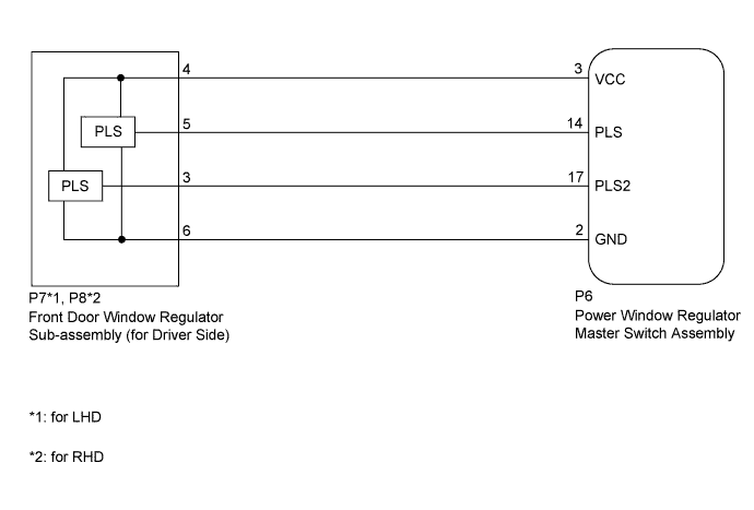
WIRING DIAGRAM
INSPECTION PROCEDURE
CHECK MANUAL UP/DOWN FUNCTION (FOR DRIVER SIDE)
CHECK LIGHT OF POWER WINDOW REGULATOR MASTER SWITCH ASSEMBLY
RESET FRONT DOOR WINDOW REGULATOR SUB-ASSEMBLY (FOR DRIVER SIDE)
CHECK HARNESS AND CONNECTOR (POWER WINDOW REGULATOR MASTER SWITCH ASSEMBLY - FRONT DOOR WINDOW REGULATOR SUB-ASSEMBLY [FOR DRIVER SIDE])
CHECK POWER WINDOW REGULATOR MASTER SWITCH ASSEMBLY (PLS, PLS2 SIGNAL)
POWER WINDOW CONTROL SYSTEM (w/ Jam Protection Function) - Auto Up / Down Function does not Operate |
DESCRIPTION
If the auto up/down function does not operate, the cause may be one or more of the following:- The recorded power window fully closed position, which is stored in the power window regulator master switch assembly, was erased as a result of: 1) the PWR H-fuse or DOOR fuse being replaced; or 2) the battery cable and the master switch's connector being disconnected.
- The power window regulator master switch assembly has a malfunction.
- The pulse sensors in the front door window regulator sub-assembly (for driver side) have a malfunction.
- The wiring between the power window regulator master switch assembly and the front door window regulator sub-assembly (for driver side) is open or short-circuited.
WIRING DIAGRAM
INSPECTION PROCEDURE
| 1.CHECK MANUAL UP/DOWN FUNCTION (FOR DRIVER SIDE) |
Check that the manual up/down function operates normally.
- OK:
- Manual up/down function operates normally.
| 2.CHECK LIGHT OF POWER WINDOW REGULATOR MASTER SWITCH ASSEMBLY |
Turn the ignition switch to ON.
Text in Illustration*A
| for LHD
| *B
| for RHD
|
*1
| AUTO Light
| -
| -
|
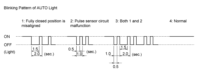
Operate the master switch's driver side power window switch for 2 seconds or more.
Check the blinking pattern of the AUTO light. Compare the blinking pattern with the illustration.
ResultBlinking Pattern
| Proceed to
|
1 or 3
| A
|
2
| B
|
4
| C
|
| 3.RESET FRONT DOOR WINDOW REGULATOR SUB-ASSEMBLY (FOR DRIVER SIDE) |
Check that the power window operates normally after reset (Toyota Fortuner RM000001DJB01KX.html).
- OK:
- Power window operates normally.
| 4.CHECK HARNESS AND CONNECTOR (POWER WINDOW REGULATOR MASTER SWITCH ASSEMBLY - FRONT DOOR WINDOW REGULATOR SUB-ASSEMBLY [FOR DRIVER SIDE]) |
Disconnect the P6 power window regulator master switch assembly connector.
Disconnect the P7*1 or P8*2 front door window regulator sub-assembly (for driver side) connector.
- *1: for LHD
- *2: for RHD
Measure the resistance according to the value(s) in the table below.
- Standard Resistance:
for LHDTester Connection
| Condition
| Specified Condition
|
P6-3 (VCC) - P7-4
| Always
| Below 1 Ω
|
P6-14 (PLS) - P7-5
| Always
| Below 1 Ω
|
P6-17 (PLS2) - P7-3
| Always
| Below 1 Ω
|
P6-2 (GND) - P7-6
| Always
| Below 1 Ω
|
P6-3 (VCC) or P7-4 - Body ground
| Always
| 10 kΩ or higher
|
P6-14 (PLS) or P7-5 - Body ground
| Always
| 10 kΩ or higher
|
P6-17 (PLS2) or P7-3 - Body ground
| Always
| 10 kΩ or higher
|
for RHDTester Connection
| Condition
| Specified Condition
|
P6-3 (VCC) - P8-4
| Always
| Below 1 Ω
|
P6-14 (PLS) - P8-5
| Always
| Below 1 Ω
|
P6-17 (PLS2) - P8-3
| Always
| Below 1 Ω
|
P6-2 (GND) - P8-6
| Always
| Below 1 Ω
|
P6-3 (VCC) or P8-4 - Body ground
| Always
| 10 kΩ or higher
|
P6-14 (PLS) or P8-5 - Body ground
| Always
| 10 kΩ or higher
|
P6-17 (PLS2) or P8-3 - Body ground
| Always
| 10 kΩ or higher
|
| | REPAIR OR REPLACE HARNESS OR CONNECTOR |
|
|
| 5.CHECK POWER WINDOW REGULATOR MASTER SWITCH ASSEMBLY (PLS, PLS2 SIGNAL) |
Remove the power window regulator master switch assembly with its connectors still connected (Toyota Fortuner RM000004ROS005X.html).
Using an oscilloscope, check the waveform.
- OK:
Tester Connection
| Switch Condition
| Specified Condition
|
P6-14 (PLS) - Body ground
| Ignition switch ON, driver side power window switch off → up or down
| Pulse waveform is output
|
P6-17 (PLS2) - Body ground
|
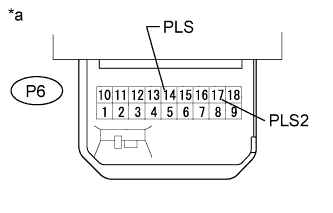
Text in Illustration*a
| Component with harness connected
(Power Window Regulator Master Switch Assembly)
|