Dtc Cb-13 Usb Over Current Detection
DESCRIPTION
WIRING DIAGRAM
INSPECTION PROCEDURE
REPLACE USB DEVICE OR "iPod"
CHECK FOR DTC
CHECK RADIO RECEIVER ASSEMBLY
CHECK HARNESS AND CONNECTOR (RADIO RECEIVER - STEREO JACK ADAPTER)
DTC CB-13 USB Over Current Detection |
DESCRIPTION
DTC Code
| DTC Detection Condition
| Trouble Area
|
CB-13
| An "iPod" or USB device overcurrent malfunction
| - "iPod" or USB device
- Harness or connector
- No. 1 stereo jack adapter assembly
- Radio receiver assembly
|
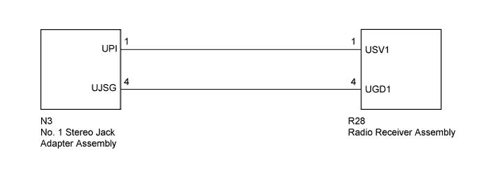
WIRING DIAGRAM
INSPECTION PROCEDURE
- NOTICE:
- The data stored on the USB device or "iPod" may be changed or lost due to malfunctions, repairs, system errors, etc. Therefore, when repairs are to be performed, explain this to the customer and obtain their consent prior to performing repairs.
| 1.REPLACE USB DEVICE OR "iPod" |
Disconnect the USB device or "iPod" from the stereo jack adapter assembly.
Turn the ignition switch off.
- HINT:
- When this DTC has been stored, it is necessary to turn off the ignition switch to make it possible for the vehicle to recognize a new device when it is connected.
Turn the ignition switch to ACC.
Connect a known good USB device or "iPod" to the stereo jack adapter assembly.
Clear the DTCs (Toyota Fortuner RM0000014CZ0B1X.html).
Check for DTCs and check if the same DTC occurs again.
- HINT:
- If DTCs are output frequently, replace the radio receiver assembly.
- OK:
- Malfunction disappears.
| OK |
|
|
|
| USB DEVICE OR "iPod" WAS DEFECTIVE |
|
| 3.CHECK RADIO RECEIVER ASSEMBLY |
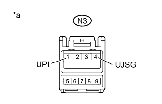
Disconnect the N3 No. 1 stereo jack adapter assembly connector.
Measure the voltage according to the value(s) in the table below.
- Standard Voltage:
Tester Connection
| Condition
| Specified Condition
|
N3-1 (UPI) - N3-4 (UJSG)
| Always
| 4.5 to 5.5 V
|
Text in Illustration*a
| Front view of wire harness connector
(to No. 1 Stereo Jack Adapter Assembly)
|
| 4.CHECK HARNESS AND CONNECTOR (RADIO RECEIVER - STEREO JACK ADAPTER) |
Disconnect the R28 radio receiver assembly connector.
Disconnect the N3 No. 1 stereo jack adapter assembly connector.
Measure the resistance according to the value(s) in the table below.
- Standard Resistance:
Tester Connection
| Condition
| Specified Condition
|
R28-1 (USV1) - N3-1 (UPI)
| Always
| Below 1 Ω
|
R28-4 (UGD1) - N3-4 (UJSG)
| Always
| Below 1 Ω
|
R28-1 (USV1) - Body ground
| Always
| 10 kΩ or higher
|
R28-4 (UGD1) - Body ground
| Always
| 10 kΩ or higher
|
| | REPAIR OR REPLACE HARNESS OR CONNECTOR |
|
|