Air Conditioning System (For Automatic Air Conditioning System) Vehicle Speed Signal Circuit
DESCRIPTION
WIRING DIAGRAM
INSPECTION PROCEDURE
CHECK AIR CONDITIONING AMPLIFIER ASSEMBLY
CHECK COMBINATION METER ASSEMBLY
CHECK HARNESS AND CONNECTOR (COMBINATION METER - AIR CONDITIONING AMPLIFIER)
AIR CONDITIONING SYSTEM (for Automatic Air Conditioning System) - Vehicle Speed Signal Circuit |
DESCRIPTION
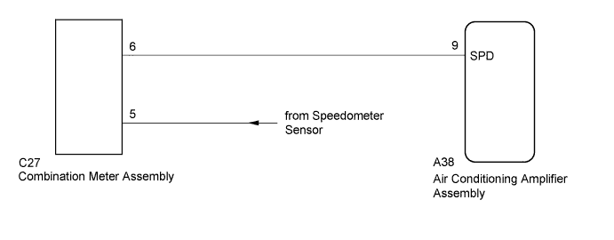
The air conditioning amplifier assembly monitors signals from the speedometer sensor via the combination meter assembly. The air conditioning amplifier assembly uses these signals to adjust the thermistor signal.
WIRING DIAGRAM
INSPECTION PROCEDURE
- HINT:
- Check that the speedometer in the combination meter assembly operates normally before inspecting the vehicle speed signal circuit (Toyota Fortuner RM0000011IY017X.html).
| 1.CHECK AIR CONDITIONING AMPLIFIER ASSEMBLY |
Remove the air conditioning amplifier assembly with its connectors still connected (Toyota Fortuner RM000001K3A018X.html).
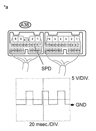
Using an oscilloscope, check the waveform of the air conditioning amplifier assembly.
Measurement ConditionItem
| Content
|
Tester Connection
| A38-9 (SPD) - Body ground
|
Tool Setting
| 5 V/DIV., 20 ms./DIV.
|
Condition
| Driving at approximately 20 km/h (12 mph)
|
- OK:
- Waveform is as shown in the illustration.
Text in Illustration*a
| Component with harness connected
(Air Conditioning Amplifier Assembly)
|
- HINT:
- As the vehicle speed increases, the wavelength becomes shorter.
| 2.CHECK COMBINATION METER ASSEMBLY |
Remove the combination meter assembly with its connector still connected (Toyota Fortuner RM000000THS01WX.html).
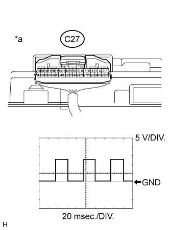
Using an oscilloscope, check the waveform of the combination meter assembly.
Measurement ConditionItem
| Content
|
Tester Connection
| C27-6 - Body ground
|
Tool setting
| 5 V/DIV., 20 ms./DIV.
|
Condition
| Vehicle is driven at approximately 20 km/h (12 mph)
|
- OK:
- Waveform is as shown in the illustration.
Text in Illustration*a
| Component with harness connected
(Combination Meter Assembly)
|
- HINT:
- As the vehicle speed increases, the wavelength becomes shorter.
| 3.CHECK HARNESS AND CONNECTOR (COMBINATION METER - AIR CONDITIONING AMPLIFIER) |
Disconnect the C27 combination meter assembly connector.
Disconnect the A38 air conditioning amplifier assembly connector.
Measure the resistance according to the value(s) in the table below.
- Standard Resistance:
Tester Connection
| Condition
| Specified Condition
|
C27-6 - A38-9 (SPD)
| Always
| Below 1 Ω
|
A38-9 (SPD) - Body ground
| Always
| 10 kΩ or higher
|
| | REPAIR OR REPLACE HARNESS OR CONNECTOR |
|
|