Meter / Gauge System Speedometer Malfunction
DESCRIPTION
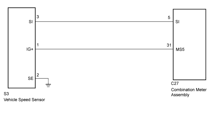
WIRING DIAGRAM
INSPECTION PROCEDURE
CHECK VEHICLE SPEED SENSOR (INPUT SIGNAL)
CHECK HARNESS AND CONNECTOR (VEHICLE SPEED SENSOR - COMBINATION METER ASSEMBLY AND BODY GROUND)
METER / GAUGE SYSTEM - Speedometer Malfunction |
DESCRIPTION
The combination meter receives vehicle speed signals from the speedometer sensor via the direct line.
WIRING DIAGRAM
INSPECTION PROCEDURE
| 1.CHECK VEHICLE SPEED SENSOR (INPUT SIGNAL) |
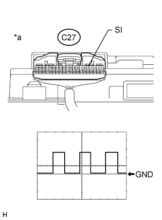
Remove the combination meter assembly with the connector(s) still connected.
Using an oscilloscope, check the signal waveform of the meter.
Measurement ConditionItem
| Content
|
Tester Connection
| C27-5 (SI) - Body ground
|
Tool Setting
| 5 V/DIV., 20 msec./DIV.
|
Condition
| Driving at approx. 20 km/h (12 mph)
|
Text in Illustration*a
| Component with harness connected
(Combination Meter Assembly)
|
- OK:
- The waveform displayed is as shown in the illustration.
- HINT:
- As the vehicle speed increases, the wavelength shortens.
| 2.CHECK HARNESS AND CONNECTOR (VEHICLE SPEED SENSOR - COMBINATION METER ASSEMBLY AND BODY GROUND) |
Disconnect the S3 vehicle speed sensor connector.
Disconnect the C27 combination meter assembly connector.
Measure the resistance according to the value(s) in the table below.
- Standard Resistance:
Tester Connection
| Condition
| Specified Condition
|
C27-5 (SI) - S3-3 (SI)
| Always
| Below 1 Ω
|
C27-31 (MS5) - S3-1 (IG+)
| Always
| Below 1 Ω
|
S3-1 (IG+) - S3-2 (SE)
| Always
| 10 kΩ or higher
|
S3-1 (IG+) - S3-3 (SI)
| Always
| 10 kΩ or higher
|
S3-2 (SE) - S3-3 (SI)
| Always
| 10 kΩ or higher
|
S3-2 (SE) - Body ground
| Always
| Below 1 Ω
|
| | REPAIR OR REPLACE HARNESS OR CONNECTOR |
|
|
| OK |
|
|
|
| REPLACE VEHICLE SPEED SENSOR |
|