Dtc C1235/35 Foreign Object Is Attached On Tip Of Front Speed Sensor Rh
DESCRIPTION
WIRING DIAGRAM
INSPECTION PROCEDURE
INSPECT EACH SPEED SENSOR
CHECK HARNESS AND CONNECTOR (SKID CONTROL ECU - EACH SPEED SENSOR)
INSPECT SKID CONTROL ECU (SENSOR INPUT)
RECONFIRM DTC
CHECK SPEED SENSOR TIP
CHECK SKID CONTROL ROTOR
REPLACE SPEED SENSOR
RECONFIRM DTC
REPLACE SKID CONTROL ROTOR
RECONFIRM DTC
DTC C1235/35 Foreign Object is Attached on Tip of Front Speed Sensor RH |
DTC C1236/36 Foreign Object is Attached on Tip of Front Speed Sensor LH |
DTC C1238/38 Foreign Object is Attached on Tip of Rear Speed Sensor RH |
DTC C1239/39 Foreign Object is Attached on Tip of Rear Speed Sensor LH |
DTC C1275/75 Abnormal Change in Output Signal of Front Speed Sensor RH (Test Mode DTC) |
DTC C1276/76 Abnormal Change in Output Signal of Front Speed Sensor LH (Test Mode DTC) |
DTC C1277/77 Abnormal Change in Output Signal of Rear Speed Sensor RH (Test Mode DTC) |
DTC C1278/78 Abnormal Change in Output Signal of Rear Speed Sensor LH (Test Mode DTC) |
DESCRIPTION
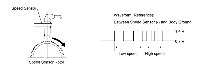
The speed sensors detect the wheel speeds and send appropriate signals to the skid control ECU. The speed sensor has a magnet behind its detection terminal, and detects changes in magnetic flux density between the peaks and valleys of the magnetic rotor teeth.The speed sensors detect those magnetic changes and send pulse signals to the skid control ECU. The ECU monitors the wheel speeds through these pulse signals to control the ABS.When foreign matter or oil adheres to the speed sensor tip or speed sensor rotor, these DTCs are output. The skid control ECU determines the existence of these conditions when an abnormal waveform is input from the sensor.These DTCs may be detected when a malfunction occurs in the connector terminals or wire harness of the speed sensor circuit.DTCs C1275/75 to C1278/78 are deleted when the speed sensor sends a vehicle speed signal or Test Mode ends. DTCs C1275/75 to C1278/78 are output only in Test Mode.- HINT:
- When the connectors between the speed sensor and skid control ECU are connected, the following waveform is output.
DTC Code
| DTC Detection Condition
| Trouble Area
|
C1235/35
C1236/36
C1238/38
C1239/39
| When either condition below is met:
- At a vehicle speed of 20 km/h (12 mph) or more, the IG1 terminal voltage is 17.4 V or less, and noise occurs in a sensor signal for 5 seconds or more.
- At a vehicle speed of 10 km/h (6 mph) or more, the IG1 terminal voltage is 17.4 V or less, and noise is detected at least once per rotor rotation for 15 seconds or more.
| - Speed sensor
- Skid control rotor
- Sensor installation
- Skid control ECU (Brake actuator assembly)
|
C1275/75
C1276/76
C1277/77
C1278/78
| Detected only during Test Mode.
| Skid control rotor
|
- HINT:
- DTCs C1235/35 and C1275/75 are for the front speed sensor RH.
- DTCs C1236/36 and C1276/76 are for the front speed sensor LH.
- DTCs C1238/38 and C1277/77 are for the rear speed sensor RH.
- DTCs C1239/39 and C1278/78 are for the rear speed sensor LH.
WIRING DIAGRAM
INSPECTION PROCEDURE
- NOTICE:
- When replacing the brake actuator assembly, perform zero point calibration (Toyota Fortuner RM000000XHR02TX.html).
- HINT:
- When C0200/31, C0205/32, C0210/33 and/or C0215/34 is output together with C1235/35, C1236/36, C1238/38, or C1239/39, inspect and repair the trouble areas indicated by C0200/31, C0205/32, C0210/33 and/or C0215/34 first (Toyota Fortuner RM000000XI9052X.html for front speed sensor, or Toyota Fortuner RM000000XIA04NX.html for rear speed sensor).
| 1.INSPECT EACH SPEED SENSOR |
Make sure that there is no looseness at the locking part and the connecting part of the connectors.
Disconnect each speed sensor connector.
Measure the resistance according to the value(s) in the table below.
- Standard Resistance:
- for Front RH:
Tester Connection
| Condition
| Specified Condition
|
1 (FR+) - Body ground
| Always
| 10 kΩ or higher
|
2 (FR-) - Body ground
| Always
| 10 kΩ or higher
|
- for Front LH:
Tester Connection
| Condition
| Specified Condition
|
1 (FL+) - Body ground
| Always
| 10 kΩ or higher
|
2 (FL-) - Body ground
| Always
| 10 kΩ or higher
|
- for Rear RH:
Tester Connection
| Condition
| Specified Condition
|
1 (RR-) - Body ground
| Always
| 10 kΩ or higher
|
2 (RR+) - Body ground
| Always
| 10 kΩ or higher
|
- for Rear LH:
Tester Connection
| Condition
| Specified Condition
|
1 (RL-) - Body ground
| Always
| 10 kΩ or higher
|
2 (RL+) - Body ground
| Always
| 10 kΩ or higher
|
ResultResult
| Proceed to
|
OK
| A
|
NG (for front speed sensor)
| B
|
NG (for rear speed sensor)
| C
|
- NOTICE:
- Check the speed sensor signal after replacement (Toyota Fortuner RM000000XHT033X.html).
| | REPLACE FRONT SPEED SENSOR |
|
|
| | REPLACE REAR SPEED SENSOR |
|
|
| 2.CHECK HARNESS AND CONNECTOR (SKID CONTROL ECU - EACH SPEED SENSOR) |
for Front Speed Sensor:
Disconnect the skid control ECU connector.
Disconnect the front speed sensor connector.
Measure the resistance according to the value(s) in the table below.
- Standard Resistance:
- for Front RH:
Tester Connection
| Condition
| Specified Condition
|
S25-7 (FR+) - S5-1 (FR+)
| Always
| Below 1 Ω
|
S25-7 (FR+) - Body ground
| Always
| 10 kΩ or higher
|
S25-6 (FR-) - S5-2 (FR-)
| Always
| Below 1 Ω
|
S25-6 (FR-) - Body ground
| Always
| 10 kΩ or higher
|
- for Front LH:
Tester Connection
| Condition
| Specified Condition
|
S25-19 (FL+) - S4-1 (FL+)
| Always
| Below 1 Ω
|
S25-19 (FL+) - Body ground
| Always
| 10 kΩ or higher
|
S25-18 (FL-) - S4-2 (FL-)
| Always
| Below 1 Ω
|
S25-18 (FL-) - Body ground
| Always
| 10 kΩ or higher
|
for Rear Speed Sensor:
Disconnect the skid control ECU connector.
Disconnect the rear speed sensor connector.
Measure the resistance according to the value(s) in the table below.
- Standard Resistance:
- for Rear RH:
Tester Connection
| Condition
| Specified Condition
|
S25-17 (RR+) - S20-2 (RR+)
| Always
| Below 1 Ω
|
S25-17 (RR+) - Body ground
| Always
| 10 kΩ or higher
|
S25-16 (RR-) - S20-1 (RR-)
| Always
| Below 1 Ω
|
S25-16 (RR-) - Body ground
| Always
| 10 kΩ or higher
|
- for Rear LH:
Tester Connection
| Condition
| Specified Condition
|
S25-5 (RL+) - S19-2 (RL+)
| Always
| Below 1 Ω
|
S25-5 (RL+) - Body ground
| Always
| 10 kΩ or higher
|
S25-4 (RL-) - S19-1 (RL-)
| Always
| Below 1 Ω
|
S25-4 (RL-) - Body ground
| Always
| 10 kΩ or higher
|
| | REPAIR OR REPLACE HARNESS OR CONNECTOR |
|
|
| 3.INSPECT SKID CONTROL ECU (SENSOR INPUT) |
for Front Speed Sensor:
Connect the skid control ECU connector.
Disconnect the front speed sensor connector.
Measure the voltage according to the value(s) in the table below.
- Standard Voltage:
- for RH:
Tester Connection
| Switch Condition
| Specified Condition
|
S5-1 (FR+) - Body ground
| Ignition switch ON
| 8 to 14 V
|
- for LH:
Tester Connection
| Switch Condition
| Specified Condition
|
S4-1 (FL+) - Body ground
| Ignition switch ON
| 8 to 14 V
|
for Rear Speed Sensor:
Connect the skid control ECU connector.
Disconnect the rear speed sensor connector.
Measure the voltage according to the value(s) in the table below.
- Standard Voltage:
- for RH:
Tester Connection
| Switch Condition
| Specified Condition
|
S20-2 (RR+) - Body ground
| Ignition switch ON
| 8 to 14 V
|
- for LH:
Tester Connection
| Switch Condition
| Specified Condition
|
S19-2 (RL+) - Body ground
| Ignition switch ON
| 8 to 14 V
|
| | REPLACE BRAKE ACTUATOR ASSEMBLY |
|
|
Turn the ignition switch off.
Clear the DTC(s) (Toyota Fortuner RM000000XHV03YX.html).
Start the engine.
Drive the vehicle at a speed of 20 km/h (12 mph) or more for at least 60 seconds.
Check if the same DTC is recorded (Toyota Fortuner RM000000XHV03YX.html).
ResultResult
| Proceed to
|
DTC output
| A
|
DTC not output
| B
|
| | CHECK FOR INTERMITTENT PROBLEMS |
|
|
Turn the ignition switch off.
Remove the front and/or rear speed sensor (for front speed sensor: Toyota Fortuner RM0000010JP00UX.html, for rear speed sensor: Toyota Fortuner RM0000010JT00SX.html).
Check the speed sensor tip.
- OK:
- No scratches or foreign matter on the sensor tip.
- HINT:
- If the sensor is contaminated with oil or other foreign material, clean the sensor.
- If there is iron powder sticking to the rotor, this will result in a malfunction, so confirm that the rotor is not contaminated with foreign material before replacing the sensor.
- NOTICE:
- Do not replace the speed sensor if no damage to the speed sensor tip is found.
- Check the speed sensor signal after cleaning or replacement (Toyota Fortuner RM000000XHT033X.html).
ResultResult
| Proceed to
|
OK
| A
|
NG (for front speed sensor)
| B
|
NG (for rear speed sensor)
| C
|
| | CLEAN OR REPLACE FRONT SPEED SENSOR |
|
|
| | CLEAN OR REPLACE REAR SPEED SENSOR |
|
|
| 6.CHECK SKID CONTROL ROTOR |
Remove the front and/or rear skid control rotor.
Check the skid control rotors.
- OK:
- No scratches, oil, or foreign matter on the rotors.
ResultResult
| Proceed to
|
OK
| A
|
NG (for front skid control rotor)
| B
|
NG (for rear skid control rotor)
| C
|
- NOTICE:
- Check the speed sensor signal after cleaning or replacement (Toyota Fortuner RM000000XHT033X.html).
| | CLEAN OR REPLACE FRONT SKID CONTROL ROTOR |
|
|
| | CLEAN OR REPLACE REAR SKID CONTROL ROTOR |
|
|
Turn the ignition switch off.
Replace the front and/or rear speed sensor (for front speed sensor: Toyota Fortuner RM0000010JP00UX.html, for rear speed sensor: Toyota Fortuner RM0000010JT00SX.html).
- NOTICE:
- Check the speed sensor signal after replacement (Toyota Fortuner RM000000XHT033X.html).
Clear the DTC(s) (Toyota Fortuner RM000000XHV03YX.html).
Start the engine.
Drive the vehicle at a speed of 20 km/h (12 mph) or more for at least 60 seconds.
Check if the same DTC is recorded (Toyota Fortuner RM000000XHV03YX.html).
ResultResult
| Proceed to
|
DTC output
| A
|
DTC not output
| B
|
| 9.REPLACE SKID CONTROL ROTOR |
Turn the ignition switch off.
Replace the front and/or rear skid control rotor.
- NOTICE:
- Check the speed sensor signal after replacement (Toyota Fortuner RM000000XHT033X.html).
Clear the DTC(s) (Toyota Fortuner RM000000XHV03YX.html).
Start the engine.
Drive the vehicle at a speed of 20 km/h (12 mph) or more for at least 60 seconds.
Check if the same DTC is recorded (Toyota Fortuner RM000000XHV03YX.html).
ResultResult
| Proceed to
|
DTC output
| A
|
DTC not output
| B
|
| A |
|
|
|
| REPLACE BRAKE ACTUATOR ASSEMBLY |
|