Dtc C1422 Master Cylinder Pressure Sensor Zero Point High Malfunction
DESCRIPTION
WIRING DIAGRAM
INSPECTION PROCEDURE
CHECK DTC
READ VALUE USING INTELLIGENT TESTER (STOP LIGHT SW)
CHECK BRAKE PEDAL AND STOP LIGHT SWITCH INSTALLATION
RECONFIRM DTC
CHECK TERMINAL VOLTAGE (STOP LIGHT POWER SOURCE CIRCUIT)
INSPECT STOP LIGHT SWITCH ASSEMBLY
CHECK TERMINAL VOLTAGE (STP TERMINAL)
DTC C1422 Master Cylinder Pressure Sensor Zero Point High Malfunction |
DESCRIPTION
Refer to DTCs C1421, C1423 and C1424 (Toyota Fortuner RM000000XIG0DQX.html).DTC Code
| DTC Detection Condition
| Trouble Area
|
C1422
| When the stop light switch is off, the PMC terminal voltage is higher than 0.86 V for 5 seconds or more.
| - STOP fuse
- Stop light switch assembly
- Stop light switch circuit
- Skid control ECU (Brake actuator assembly)
|
WIRING DIAGRAM
INSPECTION PROCEDURE
- NOTICE:
- After replacing the brake actuator assembly, perform calibration (Toyota Fortuner RM000000XHR06WX.html).
- Inspect the fuses for circuits related to this system before performing the following inspection procedure.
- Before disconnecting the connector, make sure that there are no problems with the connection.
- After disconnecting the connector, make sure that the connector case and terminals are not deformed or corroded.
Clear the DTC (Toyota Fortuner RM000000XHV0C7X.html).
Turn the ignition switch off.
Start the engine.
Drive the vehicle at a speed of 40 km/h (25 mph) or more and perform a braking test (decelerate the vehicle by depressing the brake pedal).
Check for DTCs (Toyota Fortuner RM000000XHV0C7X.html).
ResultResult
| Proceed to
|
DTC C1422 is output
| A
|
DTC C1422 and C1425 are output
| B
|
| 2.READ VALUE USING INTELLIGENT TESTER (STOP LIGHT SW) |
Turn the ignition switch off.
Connect the intelligent tester to the DLC3.
Turn the ignition switch to ON.
Turn the intelligent tester on.
Enter the following menus: Chassis / ABS/VSC/TRC / Data List.
ABS/VSC/TRCTester Display
| Measurement Item/Range
| Normal Condition
| Diagnostic Note
|
Stop Light SW
| Stop light switch / ON or OFF
| ON: Brake pedal depressed
OFF: Brake pedal released
| -
|
Check that the stop light switch display observed on the intelligent tester changes according to the brake pedal operation.
- OK:
- The intelligent tester displays ON or OFF according to brake pedal operation.
| 3.CHECK BRAKE PEDAL AND STOP LIGHT SWITCH INSTALLATION |
Turn the ignition switch off.
Check the brake pedal height and stop light switch installation (Toyota Fortuner RM0000010K601KX.html).
- OK:
- The brake pedal height and stop light switch installation are normal.
Clear the DTC (Toyota Fortuner RM000000XHV0C7X.html).
Turn the ignition switch off.
Start the engine.
Drive the vehicle at a speed of 40 km/h (25 mph) or more and perform a braking test (decelerate the vehicle by depressing the brake pedal).
Check if the same DTC is output (Toyota Fortuner RM000000XHV0C7X.html).
ResultResult
| Proceed to
|
DTC C1422 is not output
| A
|
DTC C1422 is output
| B
|
| 5.CHECK TERMINAL VOLTAGE (STOP LIGHT POWER SOURCE CIRCUIT) |
Turn the ignition switch off.
Disconnect the stop light switch assembly connector.
Measure the voltage according to the value(s) in the table below.
- Standard Voltage:
Tester Connection
| Condition
| Specified Condition
|
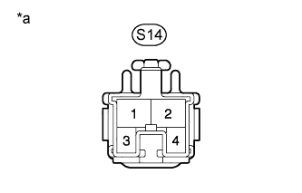
S14-2 - Body ground
| Always
| 11 to 14 V
|
Text in Illustration*a
| Front view of wire harness connector
(to Stop Light Switch Assembly)
|
| | REPAIR OR REPLACE HARNESS OR CONNECTOR |
|
|
| 6.INSPECT STOP LIGHT SWITCH ASSEMBLY |
Turn the ignition switch off.
Remove the stop light switch assembly (Toyota Fortuner RM0000018VF002X.html).
Inspect the stop light switch assembly (Toyota Fortuner RM0000018VD002X.html).
| 7.CHECK TERMINAL VOLTAGE (STP TERMINAL) |
Turn the ignition switch off.
Disconnect the skid control ECU (brake actuator assembly) connector.
Measure the voltage according to the value(s) in the table below.
- Standard Voltage:
Tester Connection
| Condition
| Specified Condition
|
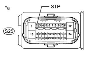
S25-2 (STP) - Body ground
| Brake pedal depressed
| 8 to 14 V
|
Brake pedal released
| Below 1.5 V
|
Text in Illustration*a
| Front view of wire harness connector
(to Skid Control ECU [Brake Actuator Assembly])
|
| | REPAIR OR REPLACE HARNESS OR CONNECTOR |
|
|