Intake Manifold -- Installation |
| 1. INSTALL INTAKE MANIFOLD |
 |
Temporarily install a new gasket and the manifold with the 2 nuts and 4 bolts.
Tighten the 2 nuts and 4 bolts in the order shown in the illustration.
- Torque:
- 29 N*m{296 kgf*cm, 21 ft.*lbf}
Connect the vacuum hose.
Connect the VSV connector.
| 2. INSTALL NO. 2 NOZZLE LEAKAGE PIPE ASSEMBLY |
Temporarily install the leakage pipe with the 3 bolts.
 |
Temporarily install a new gasket and the check valve.
Fully tighten the 3 bolts and check valve.
- Torque:
- 21 N*m{214 kgf*cm, 16 ft.*lbf} for check valve
- 13 N*m{133 kgf*cm, 10 ft.*lbf} for bolt
Connect the 2 fuel hoses.
| 3. INSTALL INJECTION PIPE SUB-ASSEMBLY |
 |
- NOTICE:
- When replacing the injector, also replace the injection pipe.
- Keep the joints of the injection pipe clean.
Temporarily install the No. 1, No. 2 and No. 3 injection pipes with the union nuts.
Install the No. 2 and No. 3 injection pipe clamps with the bolt and 2 nuts, as shown in the illustration.
- Torque:
- 5.0 N*m{51 kgf*cm, 44 in.*lbf}
- HINT:
- If the painted mark on the No. 1 injection pipe has disappeared, use the illustration as a reference to install the clamps.
Using union nut wrench, tighten the injection pipe union nuts on the common rail side.
- Torque:
- 32 N*m{326 kgf*cm, 24 ft.*lbf} for use with union nut wrench
- 35 N*m{357 kgf*cm, 26 ft.*lbf} for use without union nut wrench
- HINT:
- Use a torque wrench with a fulcrum length of 30 cm (11.81 in.).
 |
Using union nut wrench, tighten the injection pipe union nuts on the injector side.
- Torque:
- 32 N*m{326 kgf*cm, 24 ft.*lbf} for use with union nut wrench
- 35 N*m{357 kgf*cm, 26 ft.*lbf} for use without union nut wrench
- HINT:
- Use a torque wrench with a fulcrum length of 30 cm (11.81 in.).
Temporarily install the No. 4 injection pipe with the union nuts.
 |
Install 2 new injection pipe clamps with the 2 bolts.
- Torque:
- 13 N*m{133 kgf*cm, 10 ft.*lbf}
- NOTICE:
- Make sure that the inner-rubbers of the injection pipe fit inside the clamps.
- When installing the pipe, check that the inner-rubbers and the clamps are in their proper positions.
Using union nut wrench, tighten the injection pipe union nut on the common rail side.
- Torque:
- 32 N*m{326 kgf*cm, 24 ft.*lbf} for use with union nut wrench
- 35 N*m{357 kgf*cm, 26 ft.*lbf} for use without union nut wrench
- HINT:
- Use a torque wrench with a fulcrum length of 30 cm (11.81 in.).
 |
Using union nut wrench, tighten the injection pipe union nut on the injector side.
- Torque:
- 32 N*m{326 kgf*cm, 24 ft.*lbf} for use with union nut wrench
- 35 N*m{357 kgf*cm, 26 ft.*lbf} for use without union nut wrench
- HINT:
- Use a torque wrench with a fulcrum length of 30 cm (11.81 in.).
| 4. INSTALL OIL DIPSTICK GUIDE |
Install a new O-ring to the guide.
 |
Apply a small amount of clean engine oil to the O-ring.
Install the guide with the bolt.
- Torque:
- 8.0 N*m{82 kgf*cm, 71 in.*lbf}
Install the injection pipe clamp with the bolt.
- Torque:
- 5.0 N*m{51 kgf*cm, 44 in.*lbf}
| 5. INSTALL MANIFOLD STAY |
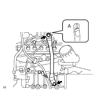 |
Install the stay with the 2 bolts.
- Torque:
- 19 N*m{194 kgf*cm, 14 ft.*lbf}
- HINT:
- The stay's indented area (labeled A) must face the manifold.
| 6. INSTALL EGR VALVE ASSEMBLY |
Install a new gasket and the EGR valve.
| 7. INSTALL NO. 1 EGR PIPE SUB-ASSEMBLY |
 |
Install 2 new gaskets and the pipe with the 2 nuts and 2 bolts.
- Torque:
- 13 N*m{133 kgf*cm, 10 ft.*lbf}
- HINT:
- The gasket's claws should be on the pipe side.
| 8. INSTALL INTAKE AIR CONNECTOR |
Install a new gasket and the air connector with the 2 nuts and bolt.
- Torque:
- 20 N*m{204 kgf*cm, 15 ft.*lbf}
 |
| 9. INSTALL THROTTLE BODY BRACKET |
Install the bracket with the 3 bolts.
- Torque:
- 20 N*m{204 kgf*cm, 15 ft.*lbf}
| 10. INSTALL DIESEL THROTTLE BODY ASSEMBLY |
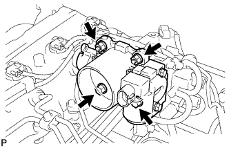 |
Install a new gasket and the throttle body with the 2 bolts and 2 nuts.
- Torque:
- 20 N*m{204 kgf*cm, 15 ft.*lbf}
Connect the throttle control motor connector.
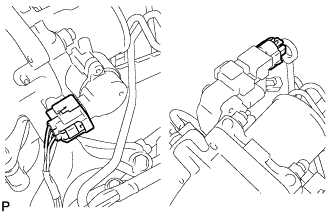 |
Connect the throttle position sensor connector.
| 11. INSTALL VACUUM SWITCHING VALVE BRACKET |
Install the bracket with the 2 bolts.
- Torque:
- 20 N*m{204 kgf*cm, 15 ft.*lbf}
 |
Connect the vacuum hoses to the 3 locations.
Connect the 2 connectors.
| 12. INSTALL CHARGE AIR COOLER ASSEMBLY WITH INTAKE AIR CONNECTOR |
Install the charge air cooler with intake air connector (Toyota Fortuner RM0000015B6002X.html).
| 13. BLEED AIR FROM FUEL SYSTEM |
| 14. CONNECT CABLE TO NEGATIVE BATTERY TERMINAL |
| 15. CHECK FOR FUEL LEAKS |
- CAUTION:
- During Active Test mode, engine speed becomes high and combustion noise becomes loud, so pay attention.
- During Active Test mode, fuel becomes high-pressured. Be extremely careful not to expose your eyes, hands, or body to escaped fuel.
Check that there are no leaks from any part of the fuel system when the engine is stopped. If there is fuel leakage, repair or replace parts as necessary.
Start the engine and check that there are no leaks from any part of the fuel system. If there is fuel leakage, repair or replace parts as necessary.
Disconnect the return hose from the common rail.
Start the engine and check for fuel leaks from the return pipe.
If there is fuel leakage, replace the common rail.
Connect the intelligent tester to the DLC3.
Start the engine and push the intelligent tester main switch on.
Select the Fuel Leak test from the Active Test mode on the intelligent tester.
If the intelligent tester is not available, fully depress the accelerator pedal quickly. Increase the engine speed to the maximum and maintain that speed for 2 seconds. Repeat this operation several times.
Check that there are no leaks from any part of the fuel system.
- NOTICE:
- A return pipe leakage of less than 10 cc (0.6 cu in.) per minute is acceptable.
Reconnect the return hose to the common rail.
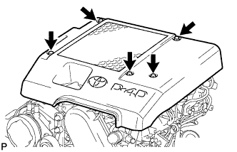
| 16. INSTALL NO. 1 ENGINE COVER SUB-ASSEMBLY |
Install the cover with the 3 bolts and 2 nuts.
- Torque:
- 7.0 N*m{71 kgf*cm, 62 in.*lbf}
 |