PERFORM ACTIVE TEST USING INTELLIGENT TESTER (OPERATE VSV FOR ACIS)
INSPECT VSV FOR ACIS (OPERATION)
CHECK HARNESS AND CONNECTOR (VSV FOR ACIS - ECM, VSV FOR ACIS - EFI NO. 2 FUSE)
INSPECT INTAKE AIR SURGE TANK (INTAKE AIR CONTROL VALVE)
DTC P0660 Intake Manifold Tuning Valve Control Circuit / Open (Bank 1)
Description DTC P0660
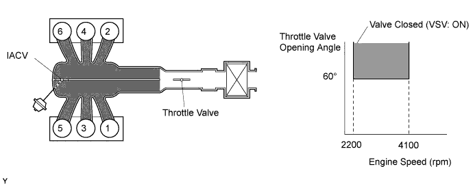
This circuit opens and closes the Intake Air Control Valve (IACV) in response to changes in the engine load in order to increase the intake efficiency (ACIS: Acoustic Control Induction System).
When the engine speed is between 2200 rpm and 4100 rpm and the throttle valve opening angle is 60° or more, the ECM supplies current to the VSV (ON status), to close the IACV. Under other conditions, the VSV is usually OFF and the IACV is open.
| DTC Code | DTC Detection Condition | Trouble Area |
| P0660 | Conditions (a) and (b) are met for 0.5 sec. or more (2 trip detection logic): (a) The voltage of terminal ACIS of the ECM is low when the VSV is OFF. (b) The engine has started. |
|
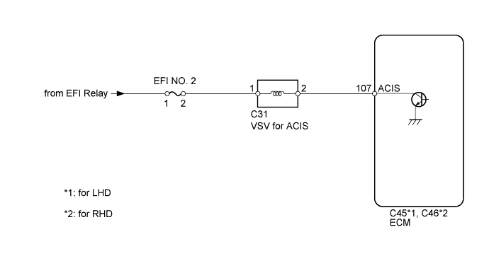
Wiring diagram
Inspection procedure
HINT:
Read freeze frame data using the intelligent tester. Freeze frame data records the engine condition when malfunctions are detected. When troubleshooting, freeze frame data can help determine if the vehicle was moving or stationary, if the engine was warmed up or not, if the air fuel ratio was lean or rich, and other data from the time the malfunction occurred.
| 1.PERFORM ACTIVE TEST USING INTELLIGENT TESTER (OPERATE VSV FOR ACIS) |

-
Disconnect the vacuum hose.
-
Connect the intelligent tester to the DLC3.
-
Turn the ignition switch to ON and turn the tester on.
-
Enter the following menus: Powertrain / Engine and ECT / Active Test / Active the VSV for Intake Control. Operate the VSV for ACIS.
-
Check the VSV operation when it is operated using the intelligent tester.
OK:
Tester Operation Specified Condition VSV ON Air from port E flows out through port F VSV OFF Air from port E flows out through air filter Result Result Proceed to NG A OK B
-
Reconnect the vacuum hose.
|
|
||||
| A | |
| 2.INSPECT VSV FOR ACIS (OPERATION) |
-
Inspect the VSV for ACIS .
|
|
||||
| OK | |
| 3.CHECK HARNESS AND CONNECTOR (VSV FOR ACIS - ECM, VSV FOR ACIS - EFI NO. 2 FUSE) |

-
Check the wire harness and connectors between the VSV for ACIS and ECM.
-
Disconnect the VSV for ACIS connector.
-
Disconnect the ECM connector.
-
Measure the resistance according to the value(s) in the table below.
Standard Resistance (Check for Open):
for LHD Tester Connection Condition Specified Condition C31-2 - C45-107 (ACIS) Always Below 1 ? for RHD Tester Connection Condition Specified Condition C31-2 - C46-107 (ACIS) Always Below 1 ? Standard Resistance (Check for Short):
for LHD Tester Connection Condition Specified Condition C31-2 or C45-107 (ACIS) - Body ground Always 10 k? or higher for RHD Tester Connection Condition Specified Condition C31-2 or C46-107 (ACIS) - Body ground Always 10 k? or higher
-
-
Check the wire harness between the VSV for ACIS and EFI NO. 2 fuse.
-
Disconnect the VSV for ACIS connector.
-
Remove the EFI NO. 2 fuse from the engine room relay block.
-
Measure the resistance according to the value(s) in the table below.
Standard Resistance (Check for Open):
Tester Connection Condition Specified Condition C31-1 - EFI NO. 2 fuse Always Below 1 ?
-
|
|
||||
| OK | |
| 4.CHECK VACUUM HOSE |
-
Check that the vacuum hose is connected correctly, and that there are no cracks, holes, damage, or looseness.
OK:
Vacuum hose is normal.
|
|
||||
| OK | |
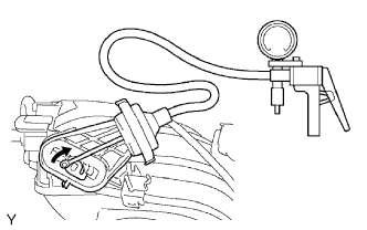
| 5.INSPECT INTAKE AIR SURGE TANK (INTAKE AIR CONTROL VALVE) |
-
Check that the lever moves when a vacuum of 26.6 kPa (200 mmHg, 7.85 in.Hg) is applied with the vacuum gauge on.
OK:
Lever moves.
-
Check that the vacuum of 26.6 kPa (200 mmHg, 7.85 in.Hg) is sustained for 1 minute in the above state.
OK:
Vacuum is sustained.
|
|
||||
| OK | |
|