DTC P1625 Idle Signal Transmitter Circuit
Description
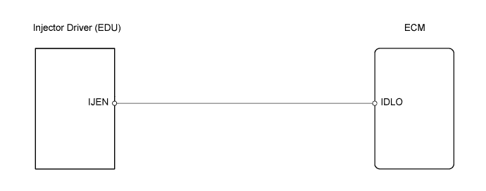
The ECM reduces injector operation speed and applied voltage to the injector to reduce the sound it produces during idling. To do this, the ECM outputs applied voltage switching signals to terminal IJEN of the EDU from terminal IDLO of the ECM.
Toyota fault code list DTC P1625
| DTC No. | DTC Detection Condition | Trouble Area |
| P1625 | When either condition below is met:
|
|
Wiring diagram
Inspection procedure
NOTICE:
After replacing the ECM, the new ECM needs registration and initialization.
| 1.CHECK WIRE HARNESS (EDU - ECM) |
-
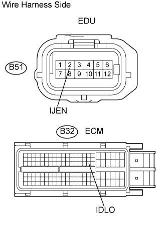
Disconnect the B51 EDU connector.
-
Disconnect the B32 ECM connector.
-
Measure the resistance of the wire harness connectors.
Standard resistance:
Tester Connection Specified Condition B51-2 (IJEN) - B32-62 (IDLO) Below 1 ? B51-2 (IJEN) - B32-62 (IDLO) - Body ground 10 k? or higher -
Reconnect the EDU connector.
-
Reconnect the ECM connector.
|
|
||||
| OK | |
| 2.REPLACE EDU |
-
Replace the EDU.
| NEXT | |
| 3.CHECK WHETHER DTC OUTPUT RECURS |
-
Connect the intelligent tester to the DLC3.
-
Turn the ignition switch on (IG) and turn the tester ON.
-
Clear DTCs.
-
Start the engine and drive the vehicle for approximately 15 minutes.
-
Enter the following menus: Powertrain / Engine and ECT / DTC.
-
Read the DTCs.
Result:Display (DTC Output) Proceed to P1625 A No output B
|
|
||||
| NG | |
|