DTC P0500 Vehicle Speed Sensor "A"
Description
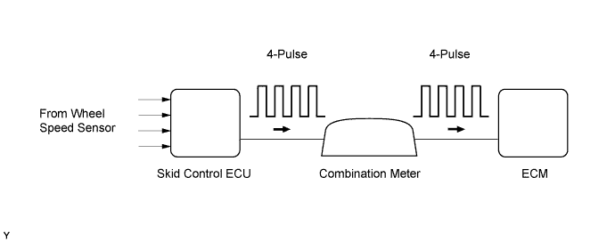
The skid control ECU outputs a signal that is proportional to vehicle speed. This signal is based on the rotation of the ABS wheel speed sensors. After this, the signal is converted into a more precise rectangular waveform by the waveform shaping circuit inside the combination meter. It is then transmitted to the ECM. The ECM determines the vehicle speed based on the frequency of this signal.
Toyota fault code list DTC P0500
| DTC No. | DTC Detection Condition | Trouble Area |
| P0500 | Conditions (a), (b) and (c) continue for 7 seconds or more: (2 trip detection logic) (a) Engine coolant temperature is more than 70°C (158°F) (b) Engine speed is between 2,000 rpm and 3,500 rpm (c) No speed signal is input to ECM |
|
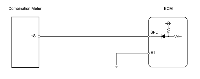
Wiring diagram
Inspection procedure
NOTICE:
After replacing the ECM, the new ECM needs registration and initialization.
| 1.CHECK OPERATION OF SPEEDOMETER |
-
Drive the vehicle.
-
Check the speedometer reading in the combination meter.
HINT:
If the vehicle speed sensor signal is inaccurate, the speedometer will show abnormal readings.
OK:
Speedometer operates normally.
|
|
||||
| OK | |
| 2.READ VALUE OF VEHICLE SPEED |
-
Connect the intelligent tester to the DLC3.
-
Start the engine and turn the tester ON.
-
Enter the following menus: Powertrain / Engine and ECT / Data List / Vehicle Speed.
-
Check the vehicle speed at an engine speed of 2,000 rpm or more while the vehicle is running.
OK:
Same value as actual vehicle speed.
|
|
||||
| NG | |
| 3.CHECK WIRE HARNESS (COMBINATION METER - ECM) |
-
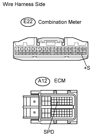
Disconnect the E22 combination meter connector.
-
Disconnect the A12 ECM connector.
-
Measure the resistance of the wire harness side connectors.
Standard resistance:
Tester Connection Specified Condition E22-39 (+S) - A12-14 (SPD) Below 1 ? E22-39 (+S) or A12-14 (SPD) - Body ground 10 k? or higher -
Reconnect the combination meter connector.
-
Reconnect the ECM connector.
|
|
||||
| OK | |
|