DTC P0120 Throttle / Pedal Position Sensor / Switch "A" Circuit
DTC P0122 Throttle / Pedal Position Sensor / Switch "A" Circuit Low Input
DTC P0123 Throttle / Pedal Position Sensor / Switch "A" Circuit High Input
Description
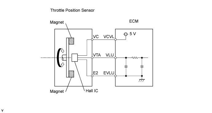
The throttle position sensor is mounted on the diesel throttle body and detects the opening angle of the throttle valve. This sensor is an electronic sensor and uses Hall-effect elements.
The ECM determines the vehicle's driving conditions from the signals input to its VLU terminal. The data is one of the inputs used for EGR control, etc.
Toyota fault code list DTC P0120, DTC P0122, DTC P0123, 2AD-FHV
| DTC No. | DTC Detection Condition | Trouble Area |
| - | Condition of DTC P0120, P0122, or P0123 continues for 0.5 seconds (open or short in throttle position sensor circuit) |
- |
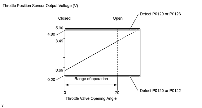
| P0120 | Throttle position sensor output (VLU) varies beyond normal operating range (less than 0.2 V or more than 4.8 V) (1 trip detection logic) |
|
| P0122 | Throttle position sensor output (VLU) is less than 0.2 V (1 trip detection logic) |
|
| P0123 | Throttle position sensor output (VLU) is more than 4.8 V (1 trip detection logic) |
|
Monitor description
When the output voltage of the throttle position sensor deviates from the normal operating range (between 0.2 V and 4.8 V) for more than 3 seconds, the ECM interprets this as a malfunction of the sensor circuit and illuminates the MIL.
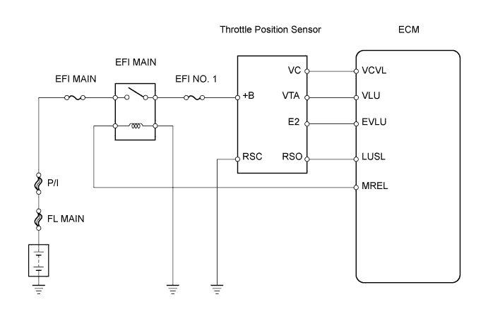
Wiring diagram
Inspection procedure
NOTICE:
After replacing the ECM, the new ECM needs registration and initialization.
HINT:
If DTCs relating to different systems are output, and they share terminal E2 as their ground, check this ground circuit first.
| 1.CHECK WIRE HARNESS (THROTTLE POSITION SENSOR - ECM) |
 |
-
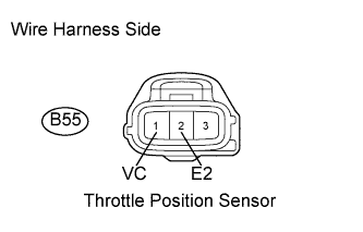
Disconnect the B55 throttle position sensor connector.
-
Disconnect the B32 ECM connector.
-
Measure the resistance of the wire harness side connectors.
Standard resistance:
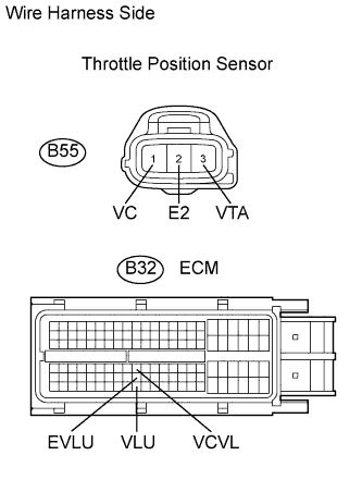
Tester Connection Specified Condition B55-1 (VC) - B32-73 (VCVL) Below 1 ? B55-3 (VTA) - B32-119 (VLU) Below 1 ? B55-2 (E2) - B32-96 (EVLU) Below 1 ? B55-1 (VC) or B32-73 (VCVL) - Body ground 10 k? or higher B55-3 (VTA) or B32-119 (VLU) - Body ground 10 k? or higher B55-2 (E2) or B32-96 (EVLU) - Body ground 10 k? or higher -
Reconnect the throttle position sensor connector.
-
Reconnect the ECM connector.
|
|
||||
| OK | |
| 2.CHECK ECM TERMINAL VOLTAGE (VC TERMINAL) |
 |
-
Disconnect the B55 throttle position sensor connector.
-
Turn the ignition switch on (IG).
-
Measure the voltage of the wire harness side connector.
Standard voltage:
Tester Connection Specified Condition B55-1 (VC) - B55-2 (E2) 4.5 to 5.5 V -
Reconnect the throttle position sensor connector.
|
|
||||
| OK | |
| 3.REPLACE DIESEL THROTTLE BODY ASSEMBLY |
-
Replace the diesel throttle body assembly.
| NEXT | |
| 4.CHECK WHETHER DTC OUTPUT RECURS |
-
Connect the intelligent tester to the DLC3.
-
Turn the ignition switch on (IG) and the tester ON.
-
Clear the DTCs.
-
Start the engine.
-
Let the engine idle for 60 seconds.
-
Repeat quick engine revving to 2,500 rpm for 30 seconds.
-
Read the DTCs.
Result:Display (DTC Output) Proceed to P0120, P0122 and/or P0123 A No output B
|
|
||||
| A | |
|