DESCRIPTION
WIRING DIAGRAM
INSPECTION PROCEDURE
CHECK HARNESS AND CONNECTOR (DRIVER SIDE JUNCTION BLOCK ASSEMBLY)
SYSTEM CHECK
CHECK HARNESS AND CONNECTOR (DRIVER SIDE JUNCTION BLOCK ASSEMBLY - RADIO RECEIVER OR RADIO AND DISPLAY OR NAVIGATION RECEIVER)
CHECK HARNESS AND CONNECTOR (DRIVER SIDE JUNCTION BLOCK ASSEMBLY - TCM)
CHECK HARNESS AND CONNECTOR (DRIVER SIDE JUNCTION BLOCK ASSEMBLY - THEFT WARNING ECU ASSEMBLY)
CHECK HARNESS AND CONNECTOR (DRIVER SIDE JUNCTION BLOCK ASSEMBLY -
AIR CONDITIONING AMPLIFIER ASSEMBLY)
CHECK ENGINE TYPE
CHECK HARNESS AND CONNECTOR (DRIVER SIDE JUNCTION BLOCK ASSEMBLY - ECM)
CHECK HARNESS AND CONNECTOR
CHECK HARNESS AND CONNECTOR (DRIVER SIDE JUNCTION BLOCK ASSEMBLY - COMBINATION METER ASSEMBLY)
CHECK COMBINATION METER ASSEMBLY
METER / GAUGE SYSTEM - Speed Signal Circuit |
DESCRIPTION
The vehicle speed signal consists of pulses sent to the combination meter assembly from the speedometer sensor. - NOTICE:
- If the speedometer operation is not normal, refer to "Speedometer Malfunction" (HILUX_TGN26 RM0000011IY01VX.html).
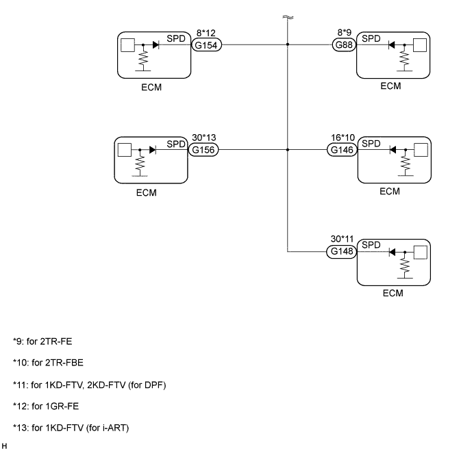
WIRING DIAGRAM
INSPECTION PROCEDURE
| 1.CHECK HARNESS AND CONNECTOR (DRIVER SIDE JUNCTION BLOCK ASSEMBLY) |
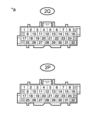
Disconnect the 2Q driver side junction block assembly connector.
Disconnect the 2P driver side junction block assembly connector.
Measure the voltage according to the value(s) in the table below.
- HINT:
- If the voltage is not as specified, it is possible that an ECU or circuit has a malfunction. The malfunctioning ECU or circuit will be diagnosed in the following steps.
- Standard Voltage:
Tester Connection
| Switch Condition
| Specified Condition
|
2Q-4 - Body ground*1, *2, *3
| Ignition switch ON
| 4.5 to 14 V
|
2Q-10 - Body ground*4, *5
| Ignition switch ON
| 4.5 to 14 V
|
2P-4 - Body ground*6
| Ignition switch ON
| 4.5 to 14 V
|
2P-10 - Body ground*7
| Ignition switch ON
| 4.5 to 14 V
|
2P-26 - Body ground
| Ignition switch ON
| 4.5 to 14 V
|
- *1: for Radio Receiver Type
- *2: for Radio and Display Type
- *3: w/ Navigation System
- *4: for 1KD-FTV
- *5: for Automatic Transmission
- *6: w/ Theft Deterrent System
- *7: w/ Automatic Air Conditioning System
Text in Illustration*a
| Front view of wire harness connector
(to Junction Connector)
|
ResultResult
| Proceed to
|
Voltage is not as specified in one circuit
| A
|
Voltage is as specified in all circuits
| B
|
Select the circuit for which the voltage was not as specified in the previous step.
ResultTester Connection
| System that Uses the Circuit
| Proceed to
|
2Q-4 - Body ground*1, *2, *3
| Audio and visual system
| A
|
2Q-10 - Body ground*4, *5
| Automatic transmission system
| B
|
2P-4 - Body ground*6
| Theft deterrent system
| C
|
2P-10 - Body ground*7
| Automatic air conditioning system
| D
|
2P-26 - Body ground
| SFI system*8 or ECD system*4, *9
| E
|
- *1: for Radio Receiver Type
- *2: for Radio and Display Type
- *3: w/ Navigation System
- *4: for 1KD-FTV
- *5: for Automatic Transmission
- *6: w/ Theft Deterrent System
- *7: w/ Automatic Air Conditioning System
- *8: for 2TR-FE, 2TR-FBE, 1GR-FE
- *9: for 2KD-FTV
| 3.CHECK HARNESS AND CONNECTOR (DRIVER SIDE JUNCTION BLOCK ASSEMBLY - RADIO RECEIVER OR RADIO AND DISPLAY OR NAVIGATION RECEIVER) |
- *1: for Radio Receiver Type
- *2: for Radio and Display Type
- *3: w/ Navigation System
Disconnect the 2Q driver side junction block assembly connector.
Disconnect the G1 radio receiver assembly*1 or G127 radio and display receiver assembly*2 connector.
Disconnect the G152 navigation receiver assembly*3 connector.
Measure the resistance according to the value(s) in the table below.
- Standard Resistance:
Tester Connection
| Condition
| Specified Condition
|
2Q-4 - G1-17 (SPD)*1
| Always
| Below 1 Ω
|
2Q-4 - G127-17 (SPD)*2
| Always
| Below 1 Ω
|
2Q-4 - G152-17 (SPD)*3
| Always
| Below 1 Ω
|
G1-17 (SPD) - Body ground*1
| Always
| 10 kΩ or higher
|
G127-17 (SPD) - Body ground*2
| Always
| 10 kΩ or higher
|
G152-17 (SPD) - Body ground*3
| Always
| 10 kΩ or higher
|
ResultResult
| Proceed to
|
NG
| A
|
OK (for Radio Receiver Type)
| B
|
OK (for Radio and Display Type)
| C
|
OK (w/ Navigation System)
| D
|
| A |
|
|
|
| REPAIR OR REPLACE HARNESS OR CONNECTOR |
|
| 4.CHECK HARNESS AND CONNECTOR (DRIVER SIDE JUNCTION BLOCK ASSEMBLY - TCM) |
Disconnect the 2Q driver side junction block assembly connector.
Disconnect the G41 TCM connector.
Measure the resistance according to the value(s) in the table below.
- Standard Resistance:
Tester Connection
| Condition
| Specified Condition
|
2Q-10 - G41-25 (SPD1)
| Always
| Below 1 Ω
|
G41-25 (SPD1) - Body ground
| Always
| 10 kΩ or higher
|
| | REPAIR OR REPLACE HARNESS OR CONNECTOR |
|
|
| 5.CHECK HARNESS AND CONNECTOR (DRIVER SIDE JUNCTION BLOCK ASSEMBLY - THEFT WARNING ECU ASSEMBLY) |
Disconnect the 2P driver side junction block assembly connector.
Disconnect the G29 theft warning ECU assembly connector.
Measure the resistance according to the value(s) in the table below.
- Standard Resistance:
Tester Connection
| Condition
| Specified Condition
|
2P-4 - G29-17 (SPD)
| Always
| Below 1 Ω
|
G29-17 (SPD) - Body ground
| Always
| 10 kΩ or higher
|
| | REPAIR OR REPLACE HARNESS OR CONNECTOR |
|
|
| 6.CHECK HARNESS AND CONNECTOR (DRIVER SIDE JUNCTION BLOCK ASSEMBLY -
AIR CONDITIONING AMPLIFIER ASSEMBLY) |
Disconnect the 2P driver side junction block assembly connector.
Disconnect the G94 air conditioning amplifier assembly connector.
Measure the resistance according to the value(s) in the table below.
- Standard Resistance:
Tester Connection
| Condition
| Specified Condition
|
2P-10 - G94-9 (SPD)
| Always
| Below 1 Ω
|
G94-9 (SPD) - Body ground
| Always
| 10 kΩ or higher
|
| | REPAIR OR REPLACE HARNESS OR CONNECTOR |
|
|
Check the engine type.
ResultResult
| Proceed to
|
for Gasoline Engine
| A
|
for Diesel Engine
| B
|
| 8.CHECK HARNESS AND CONNECTOR (DRIVER SIDE JUNCTION BLOCK ASSEMBLY - ECM) |
Disconnect the 2P driver side junction block assembly connector.
Disconnect the G154*1, G88*2 or G146*3 ECM connector.
- *1: for 1GR-FE
- *2: for 2TR-FE
- *3: for 2TR-FBE
Measure the resistance according to the value(s) in the table below.
- Standard Resistance:
for 1GR-FETester Connection
| Condition
| Specified Condition
|
2P-26 - G154-8 (SPD)
| Always
| Below 1 Ω
|
G154-8 (SPD) - Body ground
| Always
| 10 kΩ or higher
|
for 2TR-FETester Connection
| Condition
| Specified Condition
|
2P-26 - G88-8 (SPD)
| Always
| Below 1 Ω
|
G88-8 (SPD) - Body ground
| Always
| 10 kΩ or higher
|
for 2TR-FBETester Connection
| Condition
| Specified Condition
|
2P-26 - G146-16 (SPD)
| Always
| Below 1 Ω
|
G146-16 (SPD) - Body ground
| Always
| 10 kΩ or higher
|
ResultResult
| Proceed to
|
NG
| A
|
OK (for 1GR-FE)
| B
|
OK (for 2TR-FE)
| C
|
OK (for 2TR-FBE)
| D
|
| A |
|
|
|
| REPAIR OR REPLACE HARNESS OR CONNECTOR |
|
| 9.CHECK HARNESS AND CONNECTOR |
Disconnect the 2P driver side junction block assembly connector.
Disconnect the G38*1, G148*2 or G156*3 ECM connector.
- *1: for 1KD-FTV, 2KD-FTV
- *2: for 1KD-FTV, 2KD-FTV (for DPF)
- *3: for 1KD-FTV (for i-ART)
Measure the resistance according to the value(s) in the table below.
- Standard Resistance:
for 1KD-FTV, 2KD-FTVTester Connection
| Condition
| Specified Condition
|
2P-26 - G38-17 (SPD)
| Always
| Below 1 Ω
|
G38-17 (SPD) - Body ground
| Always
| 10 kΩ or higher
|
for 1KD-FTV, 2KD-FTV (for DPF)Tester Connection
| Condition
| Specified Condition
|
2P-26 - G148-30 (SPD)
| Always
| Below 1 Ω
|
G148-30 (SPD) - Body ground
| Always
| 10 kΩ or higher
|
for 1KD-FTV (for i-ART)Tester Connection
| Condition
| Specified Condition
|
2P-26 - G156-30 (SPD)
| Always
| Below 1 Ω
|
G156-30 (SPD) - Body ground
| Always
| 10 kΩ or higher
|
ResultResult
| Proceed to
|
NG
| A
|
OK (for 1KD-FTV)
| B
|
OK (for 2KD-FTV)
| C
|
| A |
|
|
|
| REPAIR OR REPLACE HARNESS OR CONNECTOR |
|
| 10.CHECK HARNESS AND CONNECTOR (DRIVER SIDE JUNCTION BLOCK ASSEMBLY - COMBINATION METER ASSEMBLY) |
Disconnect the 2Q driver side junction block assembly connector.
Disconnect the G19 combination meter assembly connector.
Measure the resistance according to the value(s) in the table below.
- Standard Resistance:
Tester Connection
| Condition
| Specified Condition
|
2Q-26 - G19-6 (+S)
| Always
| Below 1 Ω
|
G19-6 (+S) - Body ground
| Always
| 10 kΩ or higher
|
| | REPAIR OR REPLACE HARNESS OR CONNECTOR |
|
|
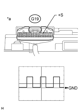
| 11.CHECK COMBINATION METER ASSEMBLY |
Check the output waveform.
Reconnect the G19 combination meter assembly connector.
Remove the combination meter assembly with the connector(s) still connected.
Connect an oscilloscope to terminal G19-6 (+S) and body ground.
Turn the ignition switch to ON.
Check the signal waveform according to the condition(s) in the table below.
Measurement ConditionItem
| Condition
|
Tester Connection
| G19-6 (+S) - Body ground
|
Tool Setting
| 5 V/DIV., 20 msec./DIV.
|
Condition
| Driving at approximately 20 km/h (12 mph)
|
Text in Illustration*a
| Component with harness connected
(Combination Meter Assembly)
|
| OK |
|
|
|
| REPLACE DRIVER SIDE JUNCTION BLOCK ASSEMBLY |
|