Dtc C1441 Performance Decline Of Brake Function
Brake. Hilux. Tgn26, 36 Kun25, 26, 35, 36 Ggn25
DESCRIPTION
INSPECTION PROCEDURE
CHECK ACCELERATOR PEDAL AND BRAKE PEDAL OPERATION
CHECK DTC AND FREEZE FRAME DATA
CLEAR DTC
CHECK BRAKE PEDAL OPERATION
CHECK BRAKE BOOSTER ASSEMBLY
CHECK BRAKE FLUID LEVEL
RECONFIRM DTC
CHECK BRAKE PEDAL LOAD SENSING SWITCH
DTC C1441 Performance Decline of Brake Function |
DESCRIPTION
The skid control ECU (brake actuator assembly) judges brake failure conditions have occurred based on the signal from the brake pedal load sensing switch (brake with switch pedal sub-assembly) and master cylinder pressure sensor (brake actuator assembly).- NOTICE:
- Do not intentionally stop the engine when driving. Even when no malfunction has occurred in the brake system, DTC C1441 will be stored when it is judged that a failure has occurred in the brake system due to a reduction in vacuum.
DTCs may be stored if one of the following occurs:- The brake pedal load sensing switch (brake with switch pedal sub-assembly) is malfunctioning (deviation in characteristics).
- The brake pedal is depressed when moving the vehicle with the engine not running and the ignition switch ON.
- Bleeding is performed with the engine running or the ignition switch ON.
- Accelerator and brake pedals depressed simultaneously.*
- HINT:
- *: The skid control ECU (brake actuator assembly) may store this DTC upon judging that a stuck on malfunction has occurred when the accelerator pedal and brake pedal are depressed simultaneously. However, this does not indicate a malfunction.
DTC Code
| DTC Detection Condition
| Trouble Area
|
C1441
| When the brake pedal load sensing switch and master cylinder pressure sensor are functioning normally and the brake pedal load sensing switch is judged as ON, the pressure signal from the master cylinder pressure sensor does not indicate an increase.
| - Brake pedal load sensing switch (Brake with switch pedal sub-assembly)
- Brake booster assembly
- Skid control ECU (Brake actuator assembly)
|
INSPECTION PROCEDURE
- NOTICE:
- After replacing the brake actuator assembly, perform calibration (HILUX_TGN26 RM000000XHR073X.html).
| 1.CHECK ACCELERATOR PEDAL AND BRAKE PEDAL OPERATION |
Interview the customer to check if the pedals were depressed simultaneously while driving or braking.
- OK:
- The pedals were not depressed simultaneously.
- HINT:
- The skid control ECU (brake actuator assembly) may store this DTC upon judging that a stuck on malfunction has occurred when the accelerator pedal and brake pedal are depressed simultaneously.
- If the pedals were depressed simultaneously, clear the DTC because it is not a malfunction.
| 2.CHECK DTC AND FREEZE FRAME DATA |
Check and record DTCs and Freeze Frame Data (HILUX_TGN26 RM000000XHV0CGX.html and HILUX_TGN26 RM000000XHY0CGX.html).
- HINT:
- Read Freeze Frame Data at the time DTC C1441 was stored, go to operation history and confirm the operating conditions.
- When reading Freeze Frame Data to confirm operating conditions, the following items can be confirmed: "F# or R# Wheel Speed", "Vehicle Speed", "Real Engine Torque" and "Accelerator Opening Angle %".
Clear the DTCs and Freeze Frame Data (HILUX_TGN26 RM000000XHV0CGX.html and HILUX_TGN26 RM000000XHY0CGX.html).
| 4.CHECK BRAKE PEDAL OPERATION |
Based on the customer problem analysis, confirm the brake pedal condition at the time the brake pedal was operated.
- Result:
Result
| Proceed to
|
The brake pedal is hard to depress.
| A
|
The brake pedal is extremely easy to depress.
| B
|
Neither of the above conditions. (Problem symptom does not occur.)
| C
|
| 5.CHECK BRAKE BOOSTER ASSEMBLY |
Check the brake booster assembly (HILUX_TGN26 RM0000010KJ00XX.html).
ResultResult
| Proceed to
|
The brake booster assembly is abnormal.
| A
|
The brake booster assembly is normal.
| B
|
- HINT:
- If the result shows that the brake booster assembly is defective, check the related components such as the brake booster, brake vacuum check valve, check valve grommet, brake booster gasket, vacuum hose and intake system for vacuum leaks or clogs.
| A |
|
|
|
| INSPECT RELATED COMPONENTS (FOR VACUUM LEAKS OR CLOGS) |
|
| 6.CHECK BRAKE FLUID LEVEL |
Check that the brake fluid level is sufficient.
- HINT:
- If the fluid level drops, check for a fluid leaks, and repair as necessary.
- Check for brake fluid leakage. (brake master cylinder, brake line, flexible hose, brake actuator, wheel cylinders, etc.)
ResultResult
| Proceed to
|
Brake fluid level is not proper.
| A
|
Brake fluid level is proper.
| B
|
- HINT:
- If brake fluid leaks are not found in components such as the brake master cylinder, brake line, flexible hose, brake actuator or wheel cylinders but the fluid level has become lower, the brake master cylinder may be leaking internally. Therefore, replace the brake master cylinder and check brake pedal operation again.
| A |
|
|
|
| CHECK AND REPAIR BRAKE FLUID LEAKS |
|
Clear the DTCs (HILUX_TGN26 RM000000XHV0CGX.html).
Start the engine.
Perform a road test
- NOTICE:
- Do not intentionally stop the engine when driving. DTC C1441 will be stored if the brake pedal is depressed when moving the vehicle with the engine not running and the ignition switch ON.
Check if the same DTC is output (HILUX_TGN26 RM000000XHV0CGX.html).
ResultResult
| Proceed to
|
DTC C1441 is not output.
| A
|
DTCs C1441 and other DTC are output.
| B
|
Only DTC C1441 is output.
| C
|
- HINT:
- If DTC C1441 and other DTCs are output simultaneously, the other DTCs may have caused the engine to malfunction, resulting in DTC C1441 to be output. Read Freeze Frame Data to confirm malfunctioning parts and repair the applicable part.
- When reading Freeze Frame Data to confirm malfunctioning parts, the following items can be confirmed: "F# or R# Wheel Speed", "Vehicle Speed", "Real Engine Torque" and "Accelerator Opening Angle %".
| | CHECK AND REPAIR APPLICABLE PART |
|
|
| |
|
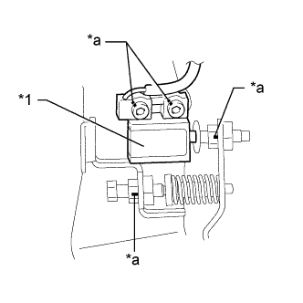
| 8.CHECK BRAKE PEDAL LOAD SENSING SWITCH |
Check that the match marks on the adjustment part of the brake pedal load sensing switch (brake with switch pedal sub-assembly) are aligned with the match marks on the bracket, nut, adjusting screw, etc.
- OK:
- The match marks on the adjustment part of the brake pedal load sensing switch (brake with switch pedal sub-assembly) are aligned with the match marks on the bracket, nut, adjusting screw, etc.
Text in Illustration *1
| Brake Pedal Load Sensing Switch (Brake with Switch Pedal Sub-assembly)
|
*a
| Match Mark
|