Sfi System (For Hatchback) Fuel Injector Circuit
DESCRIPTION
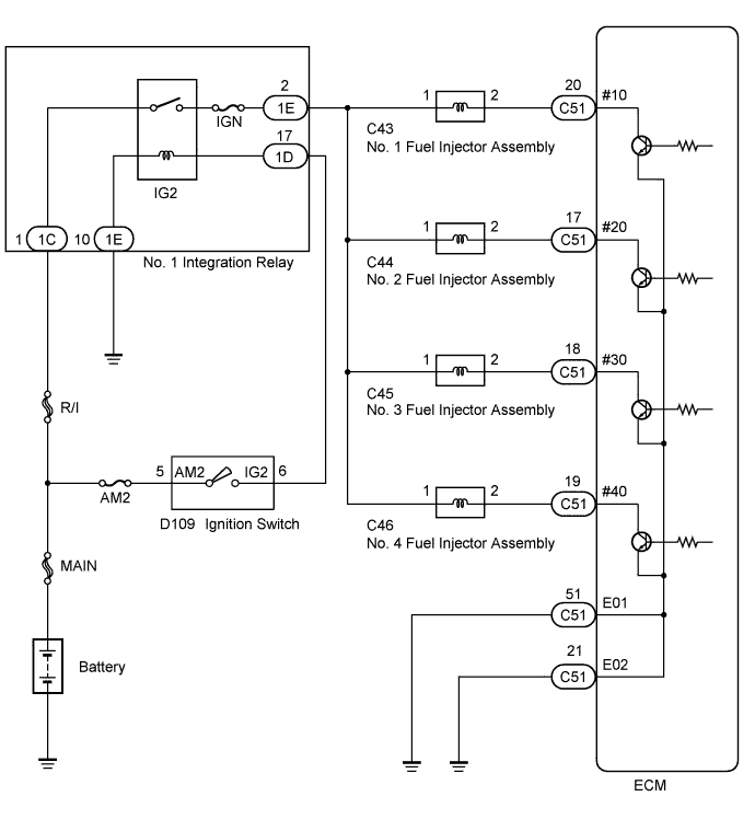
WIRING DIAGRAM
INSPECTION PROCEDURE
INSPECT FUEL INJECTOR ASSEMBLY (POWER SOURCE)
INSPECT FUEL INJECTOR ASSEMBLY (INJECTION AND VOLUME)
CHECK HARNESS AND CONNECTOR (FUEL INJECTOR ASSEMBLY - ECM)
CHECK HARNESS AND CONNECTOR (NO. 1 INTEGRATION RELAY - FUEL INJECTOR ASSEMBLY)
SFI SYSTEM (for Hatchback) - Fuel Injector Circuit |
DESCRIPTION
The fuel injectors are located on the intake port. They inject fuel into the cylinders based on the signals from the ECM.
WIRING DIAGRAM
INSPECTION PROCEDURE
- NOTICE:
- Inspect the fuses for circuits related to this system before performing the following inspection procedure.
| 1.INSPECT FUEL INJECTOR ASSEMBLY (POWER SOURCE) |
Disconnect the fuel injector assembly connectors.
Turn the ignition switch to ON.
Measure the voltage according to the value(s) in the table below.
- Standard Voltage:
Tester Connection
| Switch Condition
| Specified Condition
|
C43-1 - Body ground
| Ignition switch ON
| 11 to 14 V
|
C44-1 - Body ground
| Ignition switch ON
| 11 to 14 V
|
C45-1 - Body ground
| Ignition switch ON
| 11 to 14 V
|
C46-1 - Body ground
| Ignition switch ON
| 11 to 14 V
|
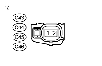
Text in Illustration*a
| Front view of wire harness connector
(to Fuel Injector)
|
| 2.INSPECT FUEL INJECTOR ASSEMBLY (INJECTION AND VOLUME) |
Check the fuel injector injection and volume (YARIS_NCP93 RM000001EDQ04MX.html).
- HINT:
- Perform "Inspection After Repair" after replacing the fuel injector assembly (YARIS_NCP93 RM000004NJD006X.html).
| 3.CHECK HARNESS AND CONNECTOR (FUEL INJECTOR ASSEMBLY - ECM) |
Disconnect the ECM connector.
Disconnect the fuel injector assembly connector.
Measure the resistance according to the value(s) in the table below.
- Standard Resistance:
Tester Connection
| Condition
| Specified Condition
|
C43-2 - C51-20 (#10)
| Always
| Below 1 Ω
|
C44-2 - C51-17 (#20)
| Always
| Below 1 Ω
|
C45-2 - C51-18 (#30)
| Always
| Below 1 Ω
|
C46-2 - C51-19 (#40)
| Always
| Below 1 Ω
|
C43-2 or C51-20 (#10) - Body ground
| Always
| 10 kΩ or higher
|
C44-2 or C51-17 (#20) - Body ground
| Always
| 10 kΩ or higher
|
C45-2 or C51-18 (#30) - Body ground
| Always
| 10 kΩ or higher
|
C46-2 or C51-19 (#40) - Body ground
| Always
| 10 kΩ or higher
|
| | REPAIR OR REPLACE HARNESS OR CONNECTOR |
|
|
| 4.CHECK HARNESS AND CONNECTOR (NO. 1 INTEGRATION RELAY - FUEL INJECTOR ASSEMBLY) |
Disconnect the fuel injector assembly connector.
Remove the No. 1 integration relay.
Measure the resistance according to the value(s) in the table below.
- Standard Resistance:
Tester Connection
| Condition
| Specified Condition
|
C43-1 - 1E-2
| Always
| Below 1 Ω
|
C44-1 - 1E-2
| Always
| Below 1 Ω
|
C45-1 - 1E-2
| Always
| Below 1 Ω
|
C46-1 - 1E-2
| Always
| Below 1 Ω
|
C43-1 or 1E-2 - Body ground
| Always
| 10 kΩ or higher
|
C44-1 or 1E-2 - Body ground
| Always
| 10 kΩ or higher
|
C45-1 or 1E-2 - Body ground
| Always
| 10 kΩ or higher
|
C46-1 or 1E-2 - Body ground
| Always
| 10 kΩ or higher
|
| | REPAIR OR REPLACE HARNESS OR CONNECTOR |
|
|