DESCRIPTION
MONITOR DESCRIPTION
MONITOR STRATEGY
TYPICAL ENABLING CONDITIONS
TYPICAL MALFUNCTION THRESHOLDS
COMPONENT OPERATING RANGE
WIRING DIAGRAM
INSPECTION PROCEDURE
CHECK HARNESS AND CONNECTOR (BATTERY - PARK/NEUTRAL POSITION SWITCH)
CHECK HARNESS AND CONNECTOR (OUTPUT SIGNAL)
INSPECT PARK/NEUTRAL POSITION SWITCH ASSEMBLY
CHECK HARNESS AND CONNECTOR (PARK/NEUTRAL POSITION SWITCH - ECM)
CHECK HARNESS AND CONNECTOR (PARK/NEUTRAL POSITION SWITCH - TRANSMISSION CONTROL SWITCH)
INSPECT SHIFT LOCK CONTROL UNIT ASSEMBLY (TRANSMISSION CONTROL SWITCH)
CHECK HARNESS AND CONNECTOR (TRANSMISSION CONTROL SWITCH - ECM)
CHECK HARNESS AND CONNECTOR (PARK/NEUTRAL POSITION SWITCH - ECM)
DTC P0705 Transmission Range Sensor Circuit Malfunction (PRNDL Input) |
DESCRIPTION
The park/neutral position switch detects the shift lever position and sends signals to the ECM.DTC No.
| DTC Detection Condition
| Trouble Area
|
P0705
| (A) Any 2 or more signals of the following are ON simultaneously (2-trip detection logic)
- STAR input signal is ON.
- R input signal is ON.
- D input signal is ON.
- 2 input signal is ON.
- L input signal is ON.
(B) Any 2 or more signals of the following are ON simultaneously (2-trip detection logic)
- P input signal is ON.
- R input signal is ON.
- N input signal is ON.
- D input signal is ON.
- 2 input signal is ON.
- L input signal is ON.
(C) All switches are OFF simultaneously for P, R, N, D, 2 and L positions (2-trip detection logic)
(D) Both 1 and 2 are met (2-trip detection logic)
- One of following is met
- STAR input signal is ON.
- P input signal is ON.
- R input signal is ON.
- N input signal is ON.
- One of following is ON.
- 3 input signal is ON.
| - Open or short in park/neutral position switch circuit
- Park/neutral position switch
- ECM
|
MONITOR DESCRIPTION
The park/neutral position switch detects the gearshift position and sends a signal to the ECM.For security, the park/neutral position switch detects the gearshift position so that engine can be started only when the vehicle is in P or N shift position.When the park/neutral position switch sends more than one signal at a time from switch positions P, R, N, D, 3, 2 or L the ECM interprets this as a fault in the switch. The ECM will turn on the MIL.
MONITOR STRATEGY
Related DTCs
| P0705: Park/neutral position switch/Verify switch input
|
Required sensors/Components
| Park/neutral position switch
|
Frequency of operation
| Continuous
|
Duration
| Condition (a) and (c): 2 seconds
Condition (b): 60 seconds
|
MIL operation
| 2 driving cycles
|
Sequence of operation
| None
|
TYPICAL ENABLING CONDITIONS
The monitor runs whenever the following DTCs are not present.
| None
|
Ignition switch
| ON
|
Battery voltage
| 10.5 V or more
|
TYPICAL MALFUNCTION THRESHOLDS
One of the following conditions is met: Condition (a), (b), (c) or (d)Condition (a):Number of following signals input simultaneously
| 2 or more
|
STAR switch
| ON
|
R switch
| ON
|
D switch
| ON
|
2 switch
| ON
|
L switch
| ON
|
Condition (b):Number of following signals input simultaneously
| 2 or more
|
P switch
| ON
|
R switch
| ON
|
N switch
| ON
|
D switch
| ON
|
2 switch
| ON
|
L switch
| ON
|
All of the following conditions are met.
Condition (c):P switch
| OFF
|
R switch
| OFF
|
N switch
| OFF
|
D switch
| OFF
|
2 switch
| OFF
|
L switch
| OFF
|
When shift lever is in P, R or N position, either of following conditions is met.
Condition (d):3 switch
| ON
|
L switch
| ON
|
COMPONENT OPERATING RANGE
Park/neutral position switch
| The park/neutral position switch sends only one signal to the ECM.
|
WIRING DIAGRAM
INSPECTION PROCEDURE
- NOTICE:
- Perform the universal trip to clear permanent DTCs (COROLLA_ZRE142 RM000000W770S5X.html).
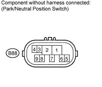
| 1.CHECK HARNESS AND CONNECTOR (BATTERY - PARK/NEUTRAL POSITION SWITCH) |
Disconnect the park/neutral position switch connector.
Turn the ignition switch to ON.
Measure the voltage according to the value(s) in the table below.
- Standard voltage:
Tester Connection
| Switch Condition
| Specified Condition
|
B88-2 (RB) - Body ground
| Ignition switch ON
| 11 to 14 V
|
| | REPAIR OR REPLACE HARNESS OR CONNECTOR |
|
|
| 2.CHECK HARNESS AND CONNECTOR (OUTPUT SIGNAL) |
Turn the ignition switch to ON.
Measure the voltage according to the value(s) in the table below.
- Standard voltage:
Tester Connection
| Switch Condition
| Specified Condition
|
B88-4 (B) - Body ground
| Ignition switch ON
| 11 to 14 V
|
- Result:
| 3.INSPECT PARK/NEUTRAL POSITION SWITCH ASSEMBLY |
Measure the resistance according to the value(s) in the table below when the shift lever is moved to each position.
- Standard resistance:
Tester Connection
| Shift Position
| Specified Condition
|
4 - 5
| P and N
| Below 1 Ω
|
Except P and N
| 10 kΩ or higher
|
2 - 6
| P
| Below 1 Ω
|
Except P
| 10 kΩ or higher
|
2 - 1
| R
| Below 1 Ω
|
Except R
| 10 kΩ or higher
|
2 - 9
| N
| Below 1 Ω
|
Except N
| 10 kΩ or higher
|
2 - 7
| D and 3
| Below 1 Ω
|
Except D and 3
| 10 kΩ or higher
|
2 - 3
| 2
| Below 1 Ω
|
Except 2
| 10 kΩ or higher
|
2 - 8
| L
| Below 1 Ω
|
Except L
| 10 kΩ or higher
|
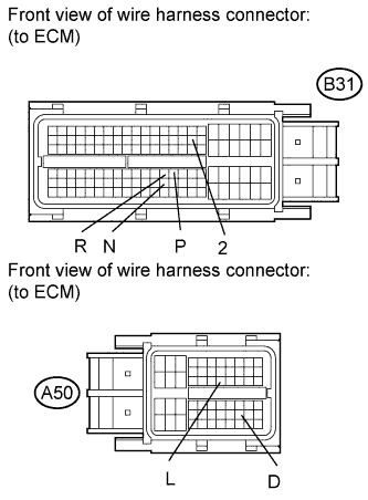
| 4.CHECK HARNESS AND CONNECTOR (PARK/NEUTRAL POSITION SWITCH - ECM) |
Connect the park/neutral position switch connector.
Disconnect the ECM connectors.
Turn the ignition switch to ON, and measure the voltage according to the value(s) in the table below when the shift lever is moved to each position.
- Standard voltage:
Tester Connection
| Shift Position
| Specified Condition
|
B31-77 (P) - Body ground
| P
| 11 to 14 V
|
Except P
| Below 1 V
|
B31-99 (N) - Body ground
| N
| 11 to 14 V
|
Except N
| Below 1 V
|
B31-76 (R) - Body ground
| R
| 11 to 14 V*
|
Except R
| Below 1 V
|
A50-47 (D) - Body ground
| D and 3
| 11 to 14 V
|
Except D and 3
| Below 1 V
|
B31-39 (2) - Body ground
| 2
| 11 to 14 V
|
Except 2
| Below 1 V
|
A50-26 (L) - Body ground
| L
| 11 to 14 V
|
Except L
| Below 1 V
|
- HINT:
- *: The voltage will drop slightly due to lighting up of the back up light.
| | REPAIR OR REPLACE HARNESS OR CONNECTOR |
|
|
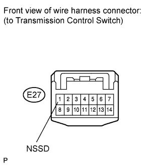
| 5.CHECK HARNESS AND CONNECTOR (PARK/NEUTRAL POSITION SWITCH - TRANSMISSION CONTROL SWITCH) |
Disconnect the transmission control switch connector of shift lock control unit assembly.
Turn the ignition switch to ON, and measure the voltage according to the value(s) in the table below when the shift lever is moved to each position.
- Standard voltage:
Tester Connection
| Shift Position
| Specified Condition
|
1 (NSSD) - Body ground
| D and 3
| 11 to 14 V
|
Except D and 3
| Below 1 V
|
| | REPAIR OR REPLACE HARNESS OR CONNECTOR |
|
|
| 6.INSPECT SHIFT LOCK CONTROL UNIT ASSEMBLY (TRANSMISSION CONTROL SWITCH) |
Measure the resistance according to the value(s) in the table below when the shift lever is moved to each position.
- Standard resistance:
Tester Connection
| Shift Position
| Specified Condition
|
1 (NSSD) - 2 (AT3)
| 3 and 2
| Below 1 Ω
|
Except 3 and 2
| 10 kΩ or higher
|
- Result:
| 7.CHECK HARNESS AND CONNECTOR (TRANSMISSION CONTROL SWITCH - ECM) |
Connect the transmission control switch connector of shift lock control unit assembly.
Turn the ignition switch to ON, and measure the voltage according to the value(s) in the table below when the shift lever is moved to each position.
- Standard voltage:
Tester Connection
| Shift Position
| Specified Condition
|
B31-124 (3) - Body ground
| 3
| 11 to 14 V
|
Except 3
| Below 1 V
|
| | REPAIR OR REPLACE HARNESS OR CONNECTOR |
|
|
| 8.CHECK HARNESS AND CONNECTOR (PARK/NEUTRAL POSITION SWITCH - ECM) |
Turn the ignition switch off.
Disconnect the ECM connectors.
Measure the resistance according to the value(s) in the table below.
- Standard resistance (Check for open):
Tester Connection
| Condition
| Specified Condition
|
B88-4 (B) - A50-25 (STAR)
| Always
| Below 1 Ω
|
- Standard resistance (Check for short):
Tester Connection
| Condition
| Specified Condition
|
B88-4 (B) or A50-25 (STAR) - Body ground
| Always
| 10 kΩ or higher
|
| | REPAIR OR REPLACE HARNESS OR CONNECTOR |
|
|