Oil Pump -- Removal |
- NOTICE:
- When replacing the injectors (including shuffling the injectors between the cylinders), common rail or cylinder head, it is necessary to replace the injection pipes with new ones.
- When replacing the fuel supply pump, common rail, cylinder block, cylinder head, cylinder head gasket or timing gear case, it is necessary to replace the fuel inlet pipe with a new one.
| 1. DISCONNECT CABLE FROM NEGATIVE BATTERY TERMINAL |
- CAUTION:
- Wait at least 90 seconds after disconnecting the cable from the negative (-) battery terminal to prevent airbag activation.
| 2. REMOVE NO. 1 ENGINE UNDER COVER (for 4WD) |
Remove the 4 bolts and under cover.
| 3. REMOVE NO. 2 ENGINE UNDER COVER (for 4WD) |
Remove the 2 bolts and under cover.
| 4. DRAIN ENGINE OIL |
Remove the oil filler cap.
Remove the oil drain plug, and drain the engine oil from the oil pan.
- NOTICE:
- Collect the oil in an oil disposal container.
| 5. DRAIN TRANSMISSION OIL OR TRANSMISSION FLUID |
R151:
Drain transmission oil (Toyota Fortuner RM0000011B2004X_01_0007.html).
R151F:
Drain transmission oil (Toyota Fortuner RM0000011AL003X_01_0010.html).
A340E:
Drain transmission fluid (Toyota Fortuner RM0000010NV00IX_01_0011.html).
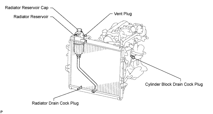
| 6. DRAIN ENGINE COOLANT |
- CAUTION:
- Do not remove the radiator reservoir cap while the engine and radiator are still hot. Pressurized, hot engine coolant and steam may be released and cause serious burns.
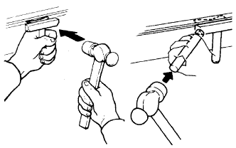
Drain the coolant by removing the reservoir cap and, using a wrench, remove the vent plug.
 |
Loosen the cylinder block drain cock plug and the radiator drain cock plug.
- HINT:
- Collect the coolant in a container and dispose of it according to the regulations in your area.
| 7. LOOSEN FUEL TANK CAP ASSEMBLY |
| 8. DRAIN FUEL |
| 9. REMOVE HOOD SUB-ASSEMBLY |
Disconnect the washer nozzle hose from the washer nozzle.
Remove the 4 bolts and hood.
| 10. REMOVE RADIATOR GRILLE |
Remove the 2 screws.
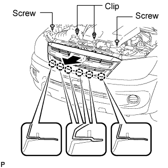 |
Using a clip remover, remove the 2 clips.
Pull the radiator grille in the direction indicated by the arrow in the illustration to detach the 6 claws and remove the radiator grille.
| 11. REMOVE BATTERY BRACKET |
| 12. REMOVE BATTERY |
| 13. REMOVE BATTERY TRAY |
| 14. REMOVE AIR CLEANER ASSEMBLY |
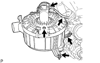 |
Disconnect the MAF meter connector and remove the clamp.
Loosen the hose clamp of the compressor inlet elbow.
Remove the 2 bolts and air cleaner.
| 15. REMOVE RADIATOR ASSEMBLY |
Remove the radiator (Toyota Fortuner RM00000144G007X.html).
| 16. REMOVE NO. 1 ENGINE COVER SUB-ASSEMBLY |
 |
Remove the 3 bolts, 2 nuts and engine cover.
| 17. REMOVE CHARGE AIR COOLER ASSEMBLY WITH INTAKE AIR CONNECTOR |
Disconnect the diesel turbo IAT sensor connector.
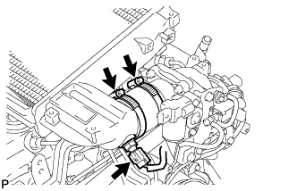 |
Loosen the 2 hose clamps of the No. 1 air hose.
Loosen the 2 hose clamps of the No. 2 air hose.
 |
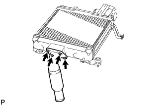
Remove the 4 bolts and CAC.
 |
Using a 22 mm deep socket wrench, remove the IAT sensor and gasket.
- HINT:
- Replace the IAT sensor if it is deformed, cracked or malfunctioning. It is not necessary to replace the IAT sensor each time the CAC is replaced.
 |
Remove the 4 bolts, intake air connector and gasket.
 |
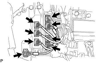
| 18. DISCONNECT HOSES AND CONNECTORS |
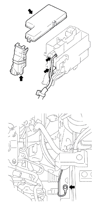 |
Remove the engine room relay block cover (upper).
Remove the No. 1 engine room relay block cover (side).
Remove the nut and disconnect the engine room J/B wire.
Disconnect the 2 engine room junction block connectors.
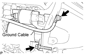
Remove the bolt and disconnect the ground cable.
for LHD:
Disconnect the 2 injector driver connectors.
 |
for RHD:
Disconnect the 2 injector driver connectors.
 |
for LHD:
Disconnect the connectors.Disconnect the turbo motor driver connector.
Disconnect the 3 TCM connector.
Disconnect the 4 ECM connector.

for RHD:
Disconnect the connectors.Disconnect the turbo motor driver connector.
Disconnect the 3 TCM connector.
Disconnect the 4 ECM connector.
Disconnect the 2 fuel hoses.
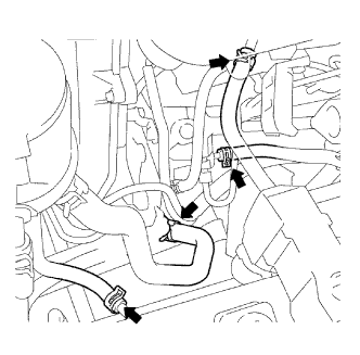 |
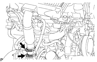
Disconnect the vacuum pump hose.
Disconnect the oil reservoir to pump hose.
Using 17 mm union nut wrench, disconnect the pressure feed tube.
 |
| 19. DISCONNECT COOLER COMPRESSOR ASSEMBLY |
Remove the 4 bolts and disconnect the cooler compressor.
- HINT:
- It is not necessary to completely remove the compressor. With the hoses connected to the compressor, hang the compressor on the vehicle body with a rope.
| 20. REMOVE STARTER ASSEMBLY |
Disconnect the starter connector.
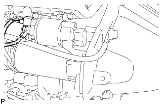 |
Remove the nut and disconnect the starter wire.
Remove the 2 bolts and starter.
 |
| 21. REMOVE FRONT EXHAUST PIPE ASSEMBLY |
Remove the 2 bolts and 2 compression springs.
Disconnect the front pipe from the outlet pipe and remove the gasket.
Remove the front pipe from the pipe support.
| 22. REMOVE FRONT PROPELLER SHAFT ASSEMBLY (for 4WD) |
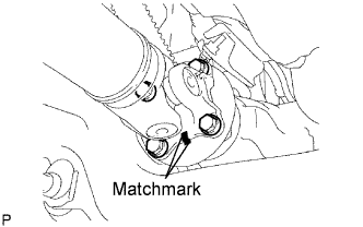 |
Place matchmarks on the yoke and differential flange.
Remove the 4 nuts, 4 bolts and 4 washers, and disconnect the propeller shaft.
Place matchmarks on the yoke and transfer flange.
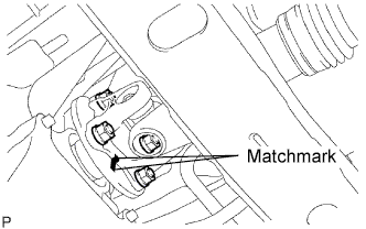 |
Remove the 4 nuts, 4 washers and front propeller shaft.
| 23. REMOVE REAR PROPELLER SHAFT ASSEMBLY |
Remove the rear propeller shaft (Toyota Fortuner RM000000ZZ3008X.html).
| 24. REMOVE TRANSMISSION ASSEMBLY |
R151:
Remove the transmission (Toyota Fortuner RM0000011B2004X.html).
R151F:
Remove the transmission (Toyota Fortuner RM0000011AL003X.html).
A340E:
Remove the transmission (Toyota Fortuner RM0000010NV00IX.html).
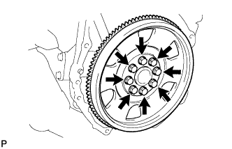
| 25. REMOVE FLYWHEEL SUB-ASSEMBLY (for Manual Transmission) |
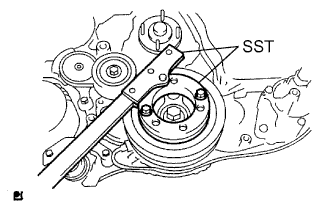 |
Using SST, hold the crankshaft.
- SST
- 09213-58013
09330-00021
Remove the 8 bolts and flywheel.
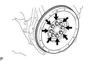 |
| 26. REMOVE DRIVE PLATE AND RING GEAR SUB-ASSEMBLY (for Automatic Transmission) |
Using SST, hold the crankshaft.
- SST
- 09213-58013
09330-00021
|
Remove the 8 bolts, drive plate spacer, and drive plate ring gear.
 |
| 27. REMOVE REAR END PLATE |
Remove the bolt and end plate.
| 28. REMOVE ENGINE ASSEMBLY |
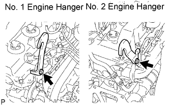 |
Set the No. 1 engine hanger and No. 2 engine hanger to the locations shown in the illustration.
- Engine hanger part No.:
Part Name Part No. No. 1 engine hanger 12284-30020 Bolt for No. 1 engine hanger 90105-T0164 or 91512-61014 No. 2 engine hanger 12282-67030 Bolt for No. 2 engine hanger 90119-T0065 or 91642-81030
- Torque:
- 25 N*m{255 kgf*cm, 18 ft.*lbf} for No. 1 engine hanger bolt
- 60 N*m{612 kgf*cm, 44 ft.*lbf} for No. 2 engine hanger bolt
- NOTICE:
- Install the engine hangers with new bolts.
Hold the engine with the engine sling device and chain block.
 |
Remove the 4 bolts and 4 nuts.
Remove the engine by operating the engine sling device and chain block.
| 29. FIX ENGINE ON ENGINE STAND |
| 30. REMOVE NO. 1 TIMING BELT COVER |
 |
Remove the bolt and water hose clamp.
Remove the wire harness clamp.
Remove the 6 bolts and timing belt cover.
| 31. REMOVE TIMING BELT |
 |
Turn the crankshaft clockwise and align the timing marks as shown in the illustration.
Uniformly loosen the 2 bolts and remove the timing belt tensioner.
 |
Remove the timing belt.
Using a 10 mm hexagon wrench, remove the bolt, timing belt idler and washer.
- HINT:
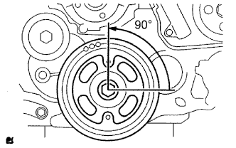
- When turning the camshaft while the timing belt is removed, turn the crankshaft 90° counterclockwise as shown in the illustration.
- When installing the timing belt, return the camshaft to the timing marks and then turn the crankshaft clockwise until it aligns with the timing marks.
| 32. REMOVE NO. 1 TIMING BELT TENSIONER ASSEMBLY |
| 33. REMOVE V-RIBBED BELT TENSIONER ASSEMBLY |
Remove the 4 bolts and tensioner.
| 34. REMOVE GENERATOR BRACKET |
| 35. REMOVE GENERATOR ASSEMBLY |
 |
Disconnect the terminal cap.
Remove the nut and generator wire.
Disconnect the generator connector.
Remove the 2 bolts and generator.
| 36. REMOVE NO. 1 COMPRESSOR MOUNTING BRACKET |
Remove the 4 bolts and mounting bracket.
| 37. REMOVE MANIFOLD STAY |
 |
Remove the 2 bolts and stay.
| 38. REMOVE FUEL INLET PIPE SUB-ASSEMBLY |
 |
Remove the bolt and clamp.
Remove the bolt and oil dipstick guide.
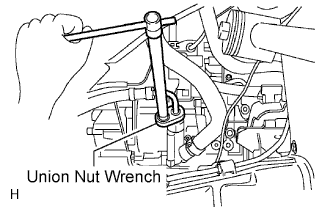
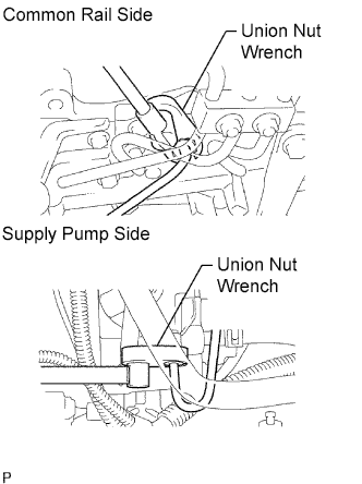
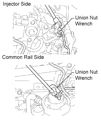
Using union nut wrench, loosen the union nuts and remove the fuel inlet pipe.
 |
| 39. REMOVE INJECTION PIPE |
 |
- NOTICE:
- After removing the fuel pipe, cover the outlets on the common rail with tape to keep out foreign matter.
- After removing the fuel pipe, put it in a plastic bag to prevent foreign matter from contaminating its injector inlet.
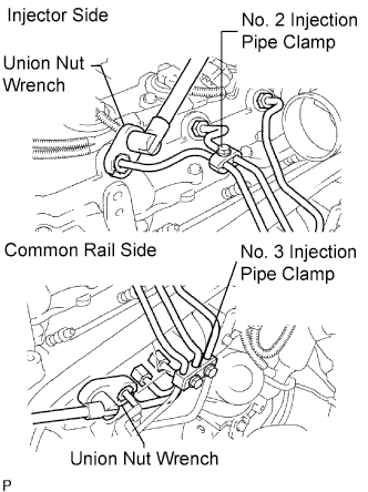
Remove the 2 nuts and No. 3 injection pipe clamp.
Remove the bolt and No. 2 injection pipe clamp.
Using union nut wrench, loosen the union nuts and remove the No. 1, No. 2 and No. 3 injection pipes.
Remove the 2 bolts and disconnect the 2 injection pipe clamps.
Using union nut wrench, loosen the union nuts and remove the No. 4 injection pipe.

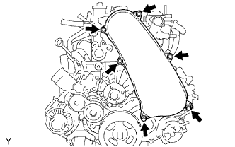
| 40. REMOVE CYLINDER HEAD COVER SUB-ASSEMBLY |
 |
Uniformly loosen the 18 cylinder head bolts in several passes in the sequence shown in the illustration. Then remove the 18 cylinder head bolts and 18 washers.
- NOTICE:
- Head warpage or cracking could result from removing bolts in the incorrect order.
Lift the cylinder head from the dowels on the cylinder block, and place the cylinder head on wooden blocks on a bench.
- HINT:
- If the cylinder head is difficult to lift, use a screwdriver to pry between the cylinder head and block.
- NOTICE:
- Be careful not to damage the contact surfaces of the cylinder head and cylinder block.
| 41. REMOVE CAMSHAFT TIMING PULLEY |
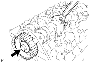 |
Remove the bolt of the camshaft timing pulley by holding the camshaft with a wrench.
- NOTICE:
- Make sure to remove the bolt of the camshaft timing pulley with the timing belt not installed.
Remove the camshaft timing pulley.
| 42. REMOVE NO. 1 TIMING BELT IDLER SUB-ASSEMBLY |
| 43. REMOVE NO. 2 TIMING BELT COVER |
Remove the 4 bolts, nut and timing belt cover.
| 44. REMOVE WATER PUMP ASSEMBLY |
Remove the 2 nuts, 5 bolts, water pump and gasket.
 |
| 45. REMOVE VACUUM PUMP ASSEMBLY |
 |
Remove the vacuum hose.
Remove the 2 nuts, vacuum pump and O-ring.
| 46. REMOVE VANE PUMP ASSEMBLY |
Remove the 2 nuts, vane pump and O-ring.
- HINT:
- It is not necessary to remove the hose from the vane pump. For the remaining removal procedures, you may put the removed assembly aside in an appropriate location.
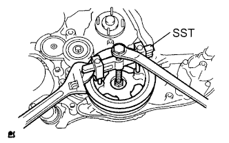
| 47. REMOVE PUMP DRIVE SHAFT PULLEY |
 |
Remove the 4 bolts, No. 2 camshaft timing pulley flange and pump drive shaft pulley.
Using SST, hold the crankshaft pulley and remove the nut and O-ring.
- SST
- 09213-58013
09330-00021
 |
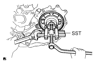
| 48. REMOVE CRANKSHAFT PULLEY |
 |
Using SST, remove the pulley bolt.
- SST
- 09213-58013
09330-00021
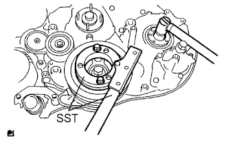
Using SST, remove the pulley.
- SST
- 09950-50013(09951-05010,09952-05010,09953-05020,09954-05021)
- NOTICE:
- Apply oil or grease to the threads and tip of SST (center bolt) before using it.
 |
| 49. REMOVE CAMSHAFT POSITION SENSOR |
Remove the bolt and sensor.
Remove the O-ring from the sensor.
| 50. REMOVE CRANKSHAFT POSITION SENSOR |
Remove the bolt and sensor.
Remove the O-ring from the sensor.
| 51. REMOVE TIMING GEAR COVER |
 |
Remove the wire harness clamp.
Remove the 14 bolts and 2 nuts.
Using a slotted screwdriver, gently separate the cover from the timing gear case.
- HINT:
- There are tiny slots that allow you to insert the slotted screwdriver tip for separating the timing gear case and its cover. Refer to the illustration for the slot locations.
- NOTICE:
- Be careful not to damage the contact surfaces of the timing gear case and its cover.
Remove the cover and O-ring.
| 52. FIX NO. 1 IDLE GEAR |
 |
Fix the sub idle gears to the idle gear with the service bolt.
- Torque:
- 8.0 N*m{82 kgf*cm, 71 in.*lbf}
- NOTICE:
- If the screw hole position of the rear sub idle gear is incorrect, rotate the crankshaft counterclockwise to correct the hole position. Then install the service bolt.
- HINT:
- The service bolt is installed to eliminate torsional force caused by the idle gear springs, which are located between the idle gear and each sub idle gear. Torsional force will cause the sub idle gear's tooth and idle gear's tooth to be out of alignment.
| 53. REMOVE CRANKSHAFT TIMING GEAR |
Remove the No. 1 crankshaft position sensor plate.
Install the service bolt to the crankshaft.
Using SST, remove the crankshaft timing gear.
- SST
- 09950-50013(09951-05010,09952-05010,09953-05020,09954-05010)
 |
| 54. REMOVE NO. 1 IDLE GEAR |
 |
Remove the 2 bolts, idle gear thrust plate and idle gear.
Remove the No. 1 idle gear shaft.
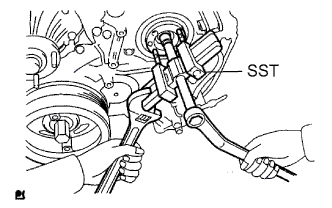
| 55. REMOVE INJECTION GEAR |
 |
Using SST, remove the injection gear.
- SST
- 09950-50013(09951-05010,09952-05010,09953-05020,09954-05021)
| 56. REMOVE FUEL SUPPLY PUMP ASSEMBLY |
Remove the bolt and clamp.
|
Remove the bolt and oil dipstick guide.
Using union nut wrench, loosen the union nuts and remove the fuel inlet pipe.
|
Disconnect the 2 fuel hoses.
 |
Disconnect the 2 connectors.
 |
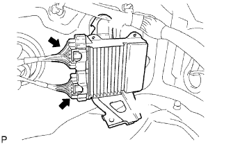
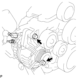
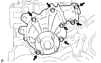
Remove the 4 bolts indicated by the arrows in the illustration.
 |
Remove the No. 2 camshaft timing pulley flange and pump drive shaft pulley.
Remove the set nut and O-ring while holding the crankshaft pulley using SST.
- SST
- 09213-58013
09330-00021
 |
Loosen the 2 nuts.
 |
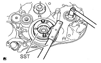
Using SST, disconnect the pump from the injection gear.
- SST
- 09950-50013(09951-05010,09952-05010,09953-05020,09954-05021)
- NOTICE:
- Apply lubricant to the threads and tip of SST (center bolt) before using it.
 |
Remove the 2 nuts and pump.
- NOTICE:
- Do not hold or carry the pump by holding the pipe.
- The pump must be kept horizontal.
Remove the O-ring.
| 57. REMOVE OIL DIPSTICK GUIDE |
Remove the bolt and oil dipstick guide.
Remove the O-ring from the oil dipstick guide.
| 58. REMOVE OIL PAN SUB-ASSEMBLY |
Remove the 22 bolts and 2 nuts.
Insert the blade of a oil pan seal cutter between the cylinder block and oil pan. Cut through the applied sealer and remove the oil pan.
- NOTICE:
- Do not use a oil pan seal cutter for the timing gear case and rear oil seal retainer.
- Be careful not to damage the oil pan flange.
 |
Remove the oil pan gasket.
Remove the 2 bolts, nut, oil strainer and gasket.
| 59. REMOVE TIMING GEAR CASE ASSEMBLY |
 |
Remove the 8 bolts and union bolt. Then remove the timing gear case and its 2 O-rings.
- NOTICE:
- Do not drop the oil pump rotor.