Manual Transmission Assembly Removal
REMOVE CABLE FROM NEGATIVE BATTERY TERMINAL
REMOVE SHIFT LEVER KNOB SUB-ASSEMBLY
REMOVE UPPER CONSOLE PANEL ASSEMBLY
REMOVE CONSOLE BOX ASSEMBLY
REMOVE SHIFT LEVER BOOT ASSEMBLY
REMOVE FLOOR SHIFT SHIFT LEVER ASSEMBLY
DRAIN MANUAL TRANSMISSION OIL
REMOVE NO. 2 FRAME CROSSMEMBER ASSEMBLY
REMOVE REAR PROPELLER SHAFT ASSEMBLY
REMOVE FRONT EXHAUST PIPE ASSEMBLY
DISCONNECT WIRE HARNESS
DISCONNECT CLUTCH RELEASE CYLINDER ASSEMBLY (for KD series)
DISCONNECT CLUTCH RELEASE CYLINDER ASSEMBLY (for 1GR-FE)
REMOVE STARTER ASSEMBLY
REMOVE NO. 3 FRAME CROSSMEMBER SUB-ASSEMBLY
REMOVE REAR NO. 1 ENGINE MOUNTING INSULATOR
REMOVE STIFFENER PLATE (for KD series)
REMOVE MANUAL TRANSMISSION ASSEMBLY
Manual Transmission Assembly -- Removal |
| 1. REMOVE CABLE FROM NEGATIVE BATTERY TERMINAL |
- CAUTION:
- Wait at least 90 seconds after disconnecting the cable from the negative (-) battery terminal to prevent airbag and seat belt pretensioner activation.
| 2. REMOVE SHIFT LEVER KNOB SUB-ASSEMBLY |
Twist the transmission shift lever knob in the direction indicated by the arrow and remove it.
for 4WD:
Twist the transfer shift lever knob in the direction indicated by the arrow and remove it.
| 3. REMOVE UPPER CONSOLE PANEL ASSEMBLY |
- NOTICE:
- Be careful not to damage the instrument panel lower and console box with the claws of the upper console panel.
Detach the 12 claws and remove the console panel.
| 4. REMOVE CONSOLE BOX ASSEMBLY |
Remove the 4 screws <F> and 2 bolts <E>.
Using a clip remover, remove the 2 clips and console box.
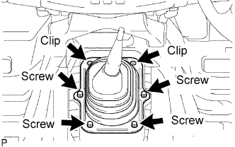
| 5. REMOVE SHIFT LEVER BOOT ASSEMBLY |
Remove the 4 screws, 2 clips and shift lever boot.
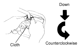
| 6. REMOVE FLOOR SHIFT SHIFT LEVER ASSEMBLY |
Cover the shift lever cap with a cloth.
Press down on the shift lever cap and rotate it counterclockwise to remove it.
Pull out the shift lever.
| 7. DRAIN MANUAL TRANSMISSION OIL |
Remove the drain plug and gasket to drain the oil.
Install a new gasket and the drain plug.
- Torque:
- 37 N*m{377 kgf*cm, 27 ft.*lbf}
| 8. REMOVE NO. 2 FRAME CROSSMEMBER ASSEMBLY |
Remove the 4 bolts, 4 nuts and frame crossmember.
| 9. REMOVE REAR PROPELLER SHAFT ASSEMBLY |
Remove the rear propeller shaft (Toyota Fortuner RM000000ZZ3008X.html).
| 10. REMOVE FRONT EXHAUST PIPE ASSEMBLY |
Remove the front exhaust pipe.
For KD series, refer to the following procedures (Toyota Fortuner RM000001213005X_01_0003.html).
For 1GR-FE, refer to the following procedures (Toyota Fortuner RM000001217003X_01_0007.html).
| 11. DISCONNECT WIRE HARNESS |
Disconnect the back-up light switch connector.
Disconnect speedometer sensor connector.
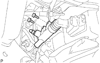
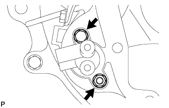
| 12. DISCONNECT CLUTCH RELEASE CYLINDER ASSEMBLY (for KD series) |
Remove the 2 bolts and disconnect the release cylinder.
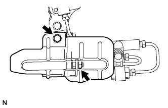
| 13. DISCONNECT CLUTCH RELEASE CYLINDER ASSEMBLY (for 1GR-FE) |
Remove the bolts, nut and release cylinder heat insulator.
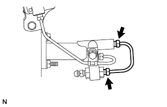
Using SST, remove the flexible tube.
- SST
- 09023-00100
- HINT:
- Use a container to catch the fluid.
Disconnect the flexible hose tube from the clutch release cylinder.
- SST
- 09023-00100
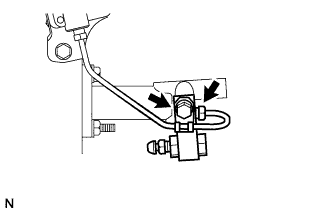
Remove the bolt and 2 way.
Remove the 2 bolts and release cylinder.
Using SST, disconnect the 2 flexible hose tubes.
- SST
- 09023-00100
| 14. REMOVE STARTER ASSEMBLY |
Remove the starter.
For KD series, refer to the following procedures (Toyota Fortuner RM0000013XL00CX.html).
For 1GR-FE, refer to the following procedures (Toyota Fortuner RM0000013XL00DX.html).
| 15. REMOVE NO. 3 FRAME CROSSMEMBER SUB-ASSEMBLY |
Support the transmission rear side with a support stand.
Remove the 4 set bolts of the rear No. 1 engine mounting insulator.
Remove the 4 bolts, 4 nuts and frame crossmember.
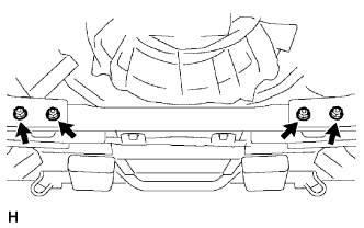
| 16. REMOVE REAR NO. 1 ENGINE MOUNTING INSULATOR |
Remove the 4 bolts and mounting insulator.
| 17. REMOVE STIFFENER PLATE (for KD series) |
Remove the 4 bolts and stiffener plate RH.
Remove the 4 bolts and stiffener plate LH.
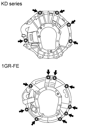
| 18. REMOVE MANUAL TRANSMISSION ASSEMBLY |
Using a transmission jack, support the transmission.
Remove the support stand from the rear side.
for KD series:
Remove the 5 bolts and transmission.
for 1GR-FE:
Remove the 9 bolts and transmission.