CHECK ANY OTHER DTCS OUTPUT (IN ADDITION TO DTC P0016, P0017, P0018 OR P0019)
PERFORM ACTIVE TEST USING INTELLIGENT TESTER (OPERATE OCV)
INSPECT CAMSHAFT OIL CONTROL VALVE ASSEMBLY
INSPECT OIL CONTROL VALVE FILTER
REPLACE CAMSHAFT TIMING GEAR ASSEMBLY
CONFIRM WHETHER MALFUNCTION HAS BEEN SUCCESSFULLY REPAIRED
DTC P0016 Crankshaft Position - Camshaft Position Correlation (Bank 1 Sensor A)
DTC P0018 Crankshaft Position - Camshaft Position Correlation (Bank 2 Sensor A)
Description DTC P0016
| DTC Code | DTC Detection Condition | Trouble Area |
| P0016 | Deviations in the crankshaft and camshaft position sensor 1 signals (2 trip detection logic). |
|
| P0018 | Deviations in the crankshaft and camshaft position sensor 2 signals (2 trip detection logic). |
Monitor description
The ECM optimizes the valve timing by using the VVT (Variable Valve Timing) system to control the intake camshaft. The VVT system includes the ECM, the camshaft Oil Control Valve (OCV) and the VVT controller.
The ECM sends a target duty-cycle control signal to the OCV. This control signal regulates the oil pressure supplied to the VVT controller. The VVT controller can advance or retard the intake camshaft. The ECM calibrates the intake valve timing by setting the intake camshaft to the most retarded angle while the engine is idling. The ECM closes the OCV to retard the cam. The ECM stores this value as the VVT learning value. When the difference between the target and actual intake valve timings is 5°CA (Crankshaft Angle) or less, the ECM stores it.
If the VVT learning value matches the following conditions, the ECM determines the existence of a malfunction in the VVT system, and stores the DTC.
- VVT learning value: Less than 22.5°CA, or more than 45.2°CA.
- The above condition continues for 18 seconds or more.
This DTC indicates that the intake camshaft has been installed toward the crankshaft at an incorrect angle, caused by factors such as the timing chain having jumped a tooth.
This monitor begins to run after the engine has idled for 5 minutes.
Wiring diagram
Refer to DTC P0335.
Refer to DTC P0340.
Inspection procedure
HINT:
Read freeze frame data using the intelligent tester. Freeze frame data records the engine condition when malfunctions are detected. When troubleshooting, freeze frame data can help determine if the vehicle was moving or stationary, if the engine was warmed up or not, if the air fuel ratio was lean or rich, and other data from the time the malfunction occurred.
1.CHECK ANY OTHER DTCS OUTPUT (IN ADDITION TO DTC P0016, P0017, P0018 OR P0019)
-
Connect the intelligent tester to the DLC3.
-
Turn the ignition switch to ON and turn the tester on.
-
Enter the following menus: Powertrain / Engine and ECT / DTC.
-
Read the DTCs.
Result Result Proceed to P0016, P0018 A P0016, P0018 and other DTCs B
|
|
||||
| A | |
2.PERFORM ACTIVE TEST USING INTELLIGENT TESTER (OPERATE OCV)
-
Connect the intelligent tester to the DLC3.
-
Start the engine and turn the tester on.
-
Warm up the engine.
-
Enter the following menus: Powertrain / Engine and ECT / Active Test / Control the VVT System (Bank 1) or Control the VVT System (Bank 2).
-
Check the engine speed while operating the camshaft Oil Control Valve (OCV) using the tester.
OK Tester Operation Specified Condition OCV OFF Normal engine speed OCV ON Engine idles roughly or stalls (soon after OCV switched from OFF to ON)
|
|
||||
| OK | |
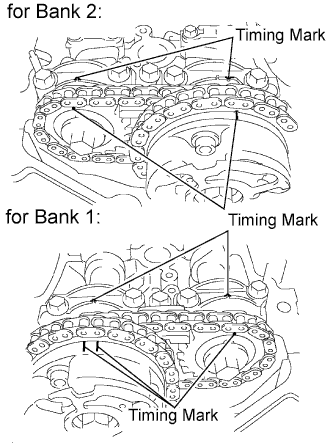
3.ADJUST VALVE TIMING
-
Remove the cylinder head cover.
-
Turn the crankshaft pulley, and align its groove with the timing mark "0" of the timing chain cover.
-
Check that the timing marks of the camshaft timing gears are aligned with the timing marks of the bearing cap as shown in the illustration.
If not, turn the crankshaft 1 revolution (360°), then align the marks as above.
OK:
Timing marks on camshaft timing gears are aligned as shown in the illustration.
|
|
||||
4.INSPECT CAMSHAFT OIL CONTROL VALVE ASSEMBLY

-
Remove the OCV.
-
Measure the resistance according to the value(s) in the table below.
Standard Resistance:
Tester Connection Condition Specified Condition 1 - 2 20°C (68°F) 6.9 to 7.9 ?
-
Apply positive battery voltage to terminal 1 and negative battery voltage to terminal 2. Check the valve operation.
OK:
Valve moves quickly.
|
|
||||
| OK | |
5.INSPECT OIL CONTROL VALVE FILTER
-
Remove the OCV filter.
-
Check that the filter is not clogged.
OK:
Filter is not clogged.
|
|
||||
| OK | |
6.REPLACE CAMSHAFT TIMING GEAR ASSEMBLY
-
Replace the camshaft timing gear assembly.
| NEXT | |
7.CONFIRM WHETHER MALFUNCTION HAS BEEN SUCCESSFULLY REPAIRED
-
In order to clear the ECM learned values for valve timing, disconnect the cable from the negative (-) battery terminal for 1 minute.
-
Connect the cable to the negative (-) battery terminal.
-
Connect the intelligent tester to the DLC3.
-
Turn the ignition switch to ON and turn the tester on.
-
Clear the DTCs.
-
Start the engine and idle it for 5 minutes.
-
Drive the vehicle in an urban area for approximately 10 minutes.
-
Enter the following menus: Powertrain / Engine and ECT / DTC / Pending.
-
Read the DTCs.
Result:
DTCs are not output.
|
|
||||
| OK | |
|