Diagnostic trouble code P0031 Oxygen (A/F) Sensor Heater Control Circuit Low (Bank 1 Sensor 1)
Diagnostic trouble code P0032 Oxygen (A/F) Sensor Heater Control Circuit High (Bank 1 Sensor 1)
Description Monitor description Wiring diagram Inspection procedureDescription. Diagnostic code P0031 P0032
HINT:
- For more information on the A/F sensor and TOYOTA D-CAT*, refer to the following procedures.
- These DTCs are related to the A/F sensor, although the titles say oxygen sensor.
*: Diesel Clean Advanced Technology.
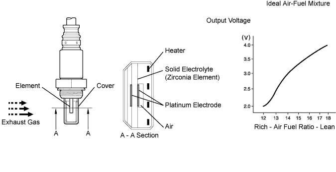
The characteristic of the A/F sensor is such that it provides an output voltage*1 that is proportional to the air-fuel ratio that it is measuring. The A/F sensor output voltage is used as feedback to allow the ECM to control the A/F mixture.
The A/F sensor is located after the Diesel Particulate-NOx Reduction (DPNR) catalytic converter. This sensor has been developed based on the structure and technology of the A/F sensor that is used for gasoline engine. The cover for the sensor electrode has been modified to suit its application in a diesel engine. This change allows the sensor to function effectively in this TOYOTA D-CAT type diesel engine, and it also avoids problems with sensor temperature and particulate matter (PM).
In order to reduce both PM and nitrogen oxides (NOx), the ECM adjusts the air-fuel ratio to a mixture that is slightly richer than that which would otherwise be used (note that this mixture is still leaner than the stoichiometric air fuel ratio). The ECM bases these adjustments on signals that it receives from the A/F sensor.
When the ECM performs DPNR catalyst regeneration (cleaning) by adding fuel using the exhaust fuel addition injector, the A/F sensor feedback is used to ensure that an appropriate air fuel ratio is maintained.
*1: This voltage change occurs only inside the computer. It is not possible to measure this voltage at the sensor. The intelligent tester can be used to monitor this voltage.
HINT:
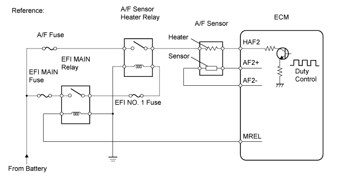
The ECM provides a pulse width modulated control circuit to adjust current through the heater. The A/F sensor heater circuit uses a relay on the B+ side of the circuit.
Engine codes explained P0031 P0032 2AD-FHV
| DTC No. | DTC Detection Condition | Trouble Area |
| P0031 | A/F sensor heater current is 0.8 A or less when the heater operates (1 trip detection logic) |
|
| P0032 | When either condition below is met:
|
|
Monitor description. Diagnostic code P0031 P0032
The inner surface of the A/F sensor element is exposed to outside air. The outer surface of the sensor element is exposed to exhaust gases. The sensor element is made of platinum coated zirconia and includes an integrated heating element. The zirconia element generates a small voltage when there is a large difference in the oxygen concentrations of the exhaust and the outside air. The platinum coating amplifies the voltage generation. When heated, the sensor becomes very efficient. If the temperature of the exhaust is low, the sensor will not generate useful voltage signals without supplemental heating. The ECM regulates the supplemental heating by using a duty-cycle approach to regulate the average current in the heater element. If the heater current is out of the normal range, the sensor's output signals will be inaccurate and the ECM cannot regulate the air-fuel ratio properly. When the heater current is out of the normal operating range, the ECM interprets this as a malfunction and sets a DTC.
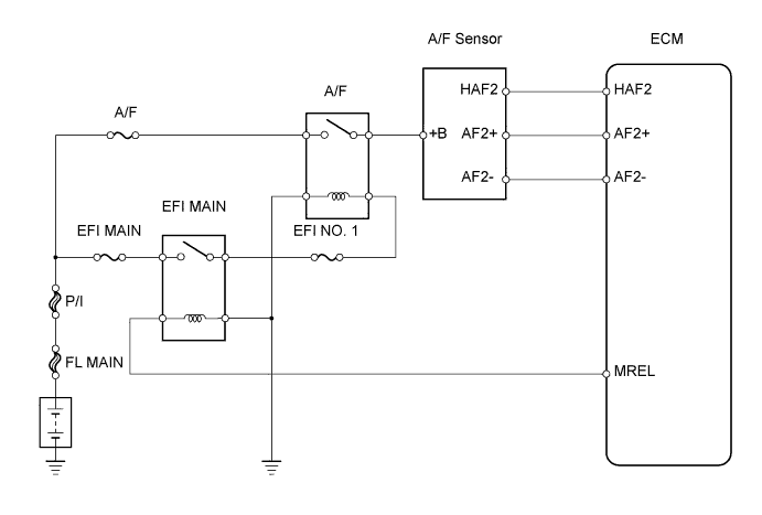
Wiring diagram. Diagnostic code P0031 P0032
Inspection procedure. Diagnostic code P0031 P0032
| 1.INSPECT AIR FUEL RATIO SENSOR (HEATER RESISTANCE) |
-
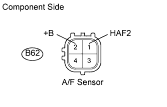
Disconnect the B62 A/F sensor connector.
-
Measure the resistance of the terminals of the A/F sensor.
Standard resistance:
| Tester Connection | Connection | Specified Condition |
| B62-1 (HAF2) - B62-2 (+B) | 20°C (68°F) | 1.8 to 3.4 ? |
-
Reconnect the A/F sensor connector.
|
|
||||
| OK | |
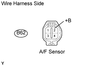
| 2.CHECK AIR FUEL RATIO SENSOR (+B VOLTAGE) |
-
Disconnect the B62 A/F sensor connector.
-
Turn the ignition switch on (IG).
-
Measure the voltage of the A/F sensor connector.
Standard voltage:
| Tester Connection | Specified Condition |
| B62-2 (+B) - Body ground | 9 to 14 V |
-
Reconnect the A/F sensor connector.
|
|
||||
| OK | |
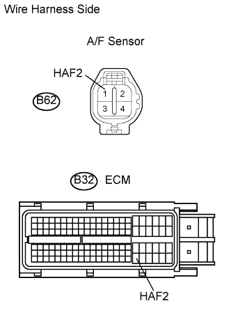
| 3.CHECK WIRE HARNESS (A/F SENSOR - ECM) |
-
Disconnect the B62 A/F sensor connector.
-
Disconnect the B32 ECM connector.
-
Measure the resistance of the wire harness side connectors.
Standard resistance:
| Tester Connection | Specified Condition |
| B62-1 (HAF2) - B32-104 (HAF2) | Below 1 ? |
| B62-1 (HAF2) or B32-104 (HAF2) - Body ground | 10 k? or higher |
-
Reconnect the A/F sensor connector.
-
Reconnect the ECM connector.
|
|
||||
| OK | |
|
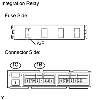
| 4.INSPECT INTEGRATION RELAY (A/F RELAY) |
-
Remove the integration relay from the engine room No. 1 relay block.
-
Inspect the A/F fuse.
-
Remove the A/F fuse from the integration relay.
-
Measure the resistance of the fuse.
Standard resistance:
Below 1 ? -
Reinstall the A/F fuse.
-
-
Inspect the A/F relay.
-
Measure the A/F relay resistance.
Standard resistance:
Tester Connection Specified Condition 1B-8 - 1C-1 10 k? or higher 1B-8 - 1C-1 Below 1 ? (Apply battery voltage to terminals 1B-6 and 1B-7) -
Reinstall the integration relay.
NG REPLACE INTEGRATION RELAY OK 5.CHECK WIRE HARNESS (A/F SENSOR - INTEGRATION RELAY - BODY GROUND) 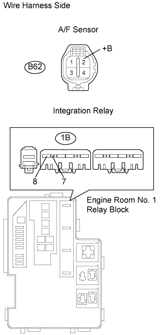
-
Check the wire harness between the A/F sensor and integration relay.
-
Disconnect the B62 A/F sensor connector.
-
Remove the integration relay from the engine room No. 1 relay block.
-
Measure the resistance of the wire harness side connector.
Standard resistance:
Tester Connection Specified Condition B62-2 (+B) - 1B-8 Below 1 ? B62-2 (+B) or 1B-8 - Body ground 10 k? or higher -
Reconnect the A/F sensor connector.
-
Check the wire harness between the integration relay and body ground.
-
Measure the resistance of the wire harness side connector.
Standard resistance:
Tester Connection Specified Condition 1B-7 - Body ground Below 1 ? -
Reinstall the integration relay.
MG REPAIR OR REPLACE HARNESS AND CONNECTOR OK REPLACE ECM -
-
-