Code P0500 Vehicle Speed Sensor "A" Signal
Description
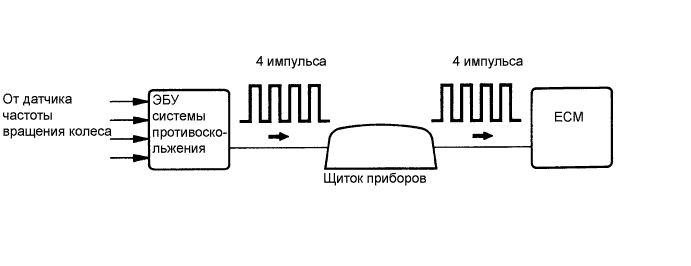
In vehicles equipped with ABS (anti-lock braking system), the speed is determined by the skid control ECU and the wheel speed sensor. The wheel speed sensor monitors the wheel speed and sends appropriate signals to the skid control ECU. The skid control ECU converts the received wheel speed signals into a 4-pulse signal and sends it to the ECM via the instrument panel. The ECM determines the vehicle speed based on the frequency of this pulse signal.
Toyota P0500 Error Code Table
| No. Errors | Error detection condition | Faulty area |
| P0500 | The ECM does not receive a vehicle speed sensor signal while the vehicle is moving. (1 trip diagnostic logic: automatic transmission) (2 trip diagnostic logic: manual transmission) |
|
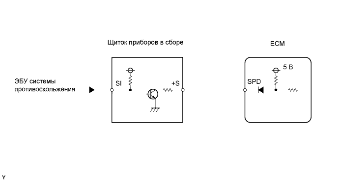
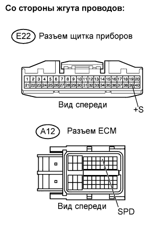
Connection diagram
Test sequence
Using a portable diagnostic tool, read the fixed parameters. These parameters reflect the state of the engine at the time the malfunction was detected. When troubleshooting, fixed parameters allow you to determine whether the car was moving at the time of the malfunction or not, whether the engine was warmed up, what the air-fuel mixture was (lean or rich), etc.
| 1. CHECK THE OPERATION OF THE SPEEDOMETER |
-
Drive the car and check that the speedometer on the instrument panel is working properly.
NOTE:- The vehicle speed sensor works properly if the speedometer readings are normal.
- If the speedometer is faulty, check it in the same manner as described for a speedometer fault.
|
|
||||
| OK | |
| 2.TAKE VEHICLE SPEED READINGS |
-
Connect the handheld diagnostic tool to the DLC3.
-
Turn the ignition switch to ON (IG) and turn on the handheld scan tool.
-
Select the following menu items: Powertrain / Engine and ECT/ Data List / Vehicle Speed.
-
Take a trip by car.
-
Read the value displayed on the scan tool.
OK:
The vehicle speeds shown on the display of the handheld diagnostic tool and the instrument panel are equal.
|
|
||||
| NG | |
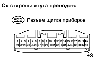
| 3.CHECK INSTRUMENT PANEL (VOLTAGE +S) |
-
Disconnect connector E22 of the instrument panel.
-
Turn on the ignition (IG).
-
Measure the voltage between the instrument panel contact and ground.
Rated voltage:Contacts for connecting a diagnostic tool Specified conditions +S (E22-39) - mass 9-14 V
-
Connect the instrument panel connector.
|
|
||||
| OK | |
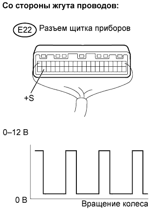
| 4.CHECK INSTRUMENT PANEL (SIGNAL FORM SPD) |
-
Move the gear shift lever to neutral.
-
Jack up the car.
-
Turn on the ignition (IG).
-
Measure the voltage between the instrument panel contact and ground by slowly turning the front wheels.
Rated voltage:Contacts for connecting a diagnostic tool Specified conditions +S (E22-39) - mass Voltage is generated intermittently NOTE:As the wheel rotates slowly, the output voltage should switch as shown in the graph.
|
|
||||
| OK | |
| 5.CHECK HARNESS AND CONNECTOR (INSTRUMENT PANEL - ECM) |
-
Disconnect connector E22 of the instrument panel.
-
Disconnect ECM connector A12.
-
Measure the resistance.
Nominal resistance (check for open):
Contacts for connecting a diagnostic tool Specified conditions +S (E22-39) - SPD (A12-8) Less than 1 ohm Nominal resistance (check for short circuit):
Contacts for connecting a diagnostic tool Specified conditions +S (E22-39) or SPD (A12-8) - weight 10 kOhm or more
-
Connect the instrument panel connector.
-
Connect the ECM connector.
|
|
||||
| OK | |
|