Dtc P0724 Brake Switch B Circuit High
DESCRIPTION
MONITOR DESCRIPTION
MONITOR STRATEGY
TYPICAL ENABLING CONDITIONS
TYPICAL MALFUNCTION THRESHOLDS
CONFIRMATION DRIVING PATTERN
WIRING DIAGRAM
INSPECTION PROCEDURE
READ VALUE USING TECHSTREAM (STOP LIGHT SWITCH)
CHECK STOP LIGHT SWITCH INSTALLATION
INSPECT STOP LIGHT SWITCH ASSEMBLY
CHECK HARNESS AND CONNECTOR (STOP LIGHT SWITCH - ECM)
DTC P0724 Brake Switch "B" Circuit High |
DESCRIPTION
The purpose of this circuit is to prevent the engine from stalling when brakes are suddenly applied while driving in lock-up condition.When the brake pedal is depressed, this switch sends a signal to the ECM. Then the ECM cancels the operation of the lock-up clutch while braking is in progress.DTC No.
| DTC Detection Condition
| Trouble Area
|
P0724
| Stop light switch remains ON even when vehicle repeats 5 cycles of STOP (less than 3 km/h (1.86 mph)) and GO (30 km/h (18.65 mph) or more) (2 trip detection logic)
| - Short in stop light switch signal circuit
- Stop light switch
- ECM
|
MONITOR DESCRIPTION
This DTC indicates that the stop light switch remains ON. When the stop light switch remains ON during "stop and go" driving, the ECM interprets this as a fault in the stop light switch and the MIL comes on and the ECM stores the DTC. The vehicle must stop (less than 3 km/h (1.86 mph)) and go (30 km/h (18.65 mph) or more) 5 times during 2 driving cycles, in order to detect a malfunction.
MONITOR STRATEGY
Related DTCs
| P0724: Stop light switch/Range check/Rationality
|
Required sensors/Components (Main)
| Stop light switch
|
Required sensors/Components (Related)
| Speed sensor
|
Frequency of Operation
| Continuous
|
Duration
| 5 times
|
MIL Operation
| 2 driving cycles
|
Sequence of Operation
| None
|
TYPICAL ENABLING CONDITIONS
The stop light switch remains ON during GO and STOP 5 times.GO and STOP are defined as follows;Monitor runs whenever following DTCs not present
| None
|
Battery voltage
| 8 V or higher
|
Starter
| OFF
|
Ignition switch
| ON
|
GO: Vehicle speed
| 30 km/h (18.65 mph) or more
|
STOP: Vehicle speed
| Less than 3 km/h (1.86 mph)
|
TYPICAL MALFUNCTION THRESHOLDS
Stop light switch status
| Stuck ON
|
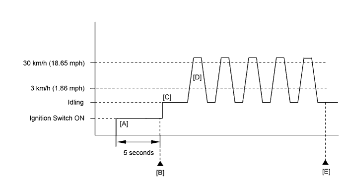
CONFIRMATION DRIVING PATTERN
- Connect the Techstream to the DLC3.
- Turn the ignition switch to ON and turn the Techstream on.
- Clear DTCs (even if no DTCs are stored, perform the clear DTC operation).
- Turn the ignition switch off and wait for at least 30 seconds.
- Turn the ignition switch to ON and turn the Techstream on [A].
- Wait for 5 seconds.
- Enter the following menus: Powertrain / Engine and ECT / Trouble Codes [B].
- Read pending DTCs.
- HINT:
- If a pending DTC is output, the system is malfunctioning.
- If a pending DTC is not output, perform the following procedure.
- Enter the following menus: Powertrain / Engine and ECT / Utility / All Readiness.
- Input the DTC: P0724.
- Check the DTC judgment result.
Techstream Display
| Description
|
NORMAL
| - DTC judgment completed
- System normal
|
ABNORMAL
| - DTC judgment completed
- System abnormal
|
INCOMPLETE
| - DTC judgment not completed
- Perform driving pattern after confirming DTC enabling conditions
|
N/A
| - Unable to perform DTC judgment
- Number of DTCs which do not fulfill DTC preconditions has reached ECU memory limit
|
- HINT:
- If the judgment result shows NORMAL, the system is normal.
- If the judgment result shows ABNORMAL, the system has a malfunction.
- If the judgment result shows INCOMPLETE or N/A, perform steps [C] through [E].
- Start the engine [C].
- Accelerate the vehicle to 30 km/h (18.65 mph) or more, depress the brake pedal and decelerate the vehicle to 3 km/h (1.86 mph) or less [D]. Repeat step [D] 5 times.
- CAUTION:
- When performing the confirmation driving pattern, obey all speed limits and traffic laws.
- Check the DTC judgment result [E].
- If the test result is INCOMPLETE or N/A and no pending DTC is output, perform a universal trip and check for permanent DTCs (YARIS_NCP93 RM000000PDK0QGX.html).
- HINT:
- If a permanent DTC is output, the system is malfunctioning.
- If no permanent DTC is output, the system is normal.
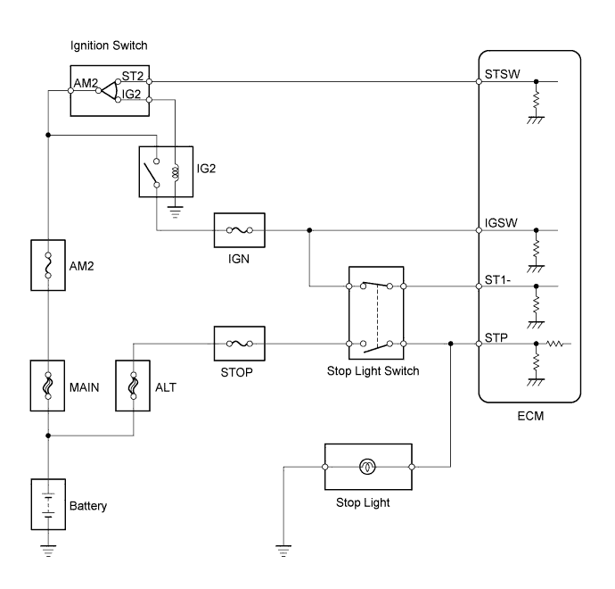
WIRING DIAGRAM
INSPECTION PROCEDURE
- NOTICE:
- Inspect the fuses for circuits related to this system before performing the following inspection procedure.
- HINT:
- Read freeze frame data using the Techstream. The ECM records vehicle and driving condition information as freeze frame data the moment a DTC is stored. When troubleshooting, freeze frame data can help determine if the vehicle was moving or stationary, if the engine was warmed up or not, if the air fuel ratio was lean or rich, and other data from the time the malfunction occurred.
- Using the Techstream, the Data List item "Stop Light Switch" and "ST1" can be read (YARIS_NCP93 RM000000XCT0KEX_03.html).
| 1.READ VALUE USING TECHSTREAM (STOP LIGHT SWITCH) |
Connect the Techstream to the DLC3.
Turn the ignition switch to ON.
Turn the Techstream on.
Enter the following menus: Powertrain / Engine and ECT / Data List / Stop Light Switch.
Read the values displayed on the Techstream.
- OK:
Item
| Measurement Item: Range (display)
| Normal Condition
|
Stop Light Switch
| Stop light switch status:
ON or OFF
| - ON: Brake pedal is depressed
- OFF: Brake pedal is released
|
| 2.CHECK STOP LIGHT SWITCH INSTALLATION |
Check the stop light switch installation (YARIS_NCP93 RM000001DKQ022X.html).
- OK:
- Stop light switch is installed correctly.
ResultResult
| Proceed to
|
OK
| A
|
NG
| B
|
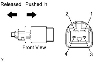
| 3.INSPECT STOP LIGHT SWITCH ASSEMBLY |
Remove the stop light switch assembly.
Check the resistance.
- Standard resistance:
Tester Connections
| Switch Positions
| Specified Conditions
|
1 - 2
| Switch pin released
| Below 1 Ω
|
Switch pin pushed in
| 10 kΩ or higher
|
3 - 4
| Switch pin released
| 10 kΩ or higher
|
Switch pin pushed in
| Below 1 Ω
|
Reinstall the stop light switch assembly.
ResultResult
| Proceed to
|
OK
| A
|
NG
| B
|
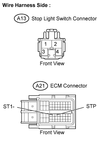
| 4.CHECK HARNESS AND CONNECTOR (STOP LIGHT SWITCH - ECM) |
Disconnect the A21 ECM connector.
Disconnect the A13 stop light switch connector.
Check the resistance.
- Standard resistance (Check for open):
Tester Connections
| Specified Conditions
|
STP (A21-36) - Stop light switch (A13-1)
| Below 1 Ω
|
ST1- (A21-35) - Stop light switch (A13-4)
|
- Standard resistance (Check for short):
Tester Connections
| Specified Conditions
|
STP (A21-36) or Stop light switch (A13-1) - Body ground
| 10 kΩ or higher
|
ST1- (A21-35) or Stop light switch (A13-4) - Body ground
|
Reconnect the ECM connector.
Reconnect the stop light switch connector.
| | REPAIR OR REPLACE HARNESS OR CONNECTOR |
|
|