Sfi System (For Sedan) Fuel Pump Control Circuit
DESCRIPTION
WIRING DIAGRAM
INSPECTION PROCEDURE
PERFORM ACTIVE TEST USING TECHSTREAM (CONTROL THE FUEL PUMP/SPEED)
INSPECT MAIN BODY ECU (C/OPN RELAY INPUT VOLTAGE)
CHECK HARNESS AND CONNECTOR (MAIN BODY ECU - INTEGRATION RELAY)
INSPECT MAIN BODY ECU (C/OPN RELAY)
CHECK HARNESS AND CONNECTOR (MAIN BODY ECU - ECM)
CHECK HARNESS AND CONNECTOR (C/OPN RELAY - FUEL PUMP - BODY GROUND)
INSPECT FUEL PUMP
READ VALUE USING TECHSTREAM (STARTER SIGNAL)
READ VALUE USING TECHSTREAM (ENGINE SPEED)
SFI SYSTEM (for Sedan) - Fuel Pump Control Circuit |
DESCRIPTION
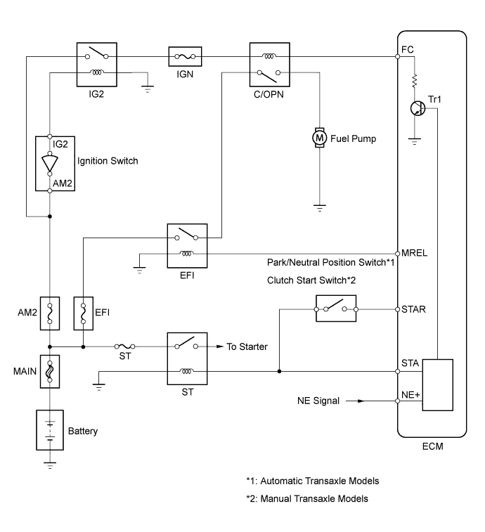
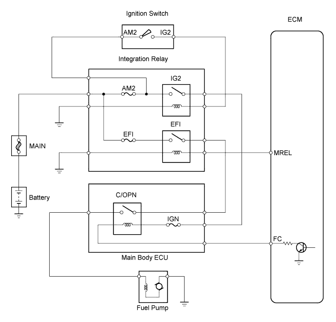
When the engine is cranked, the starter relay drive signal output from the STAR terminal of the ECM is input into the STA terminal of the ECM, and NE signal generated by the crankshaft position sensor is also input into the NE+ terminal. Thus, the ECM interprets that the engine is cranked, and turns the transistor Tr1 in the ECM internal circuit ON. The current flows to the C/OPN (Circuit Opening) relay by turning the Tr1 ON. Then, the fuel pump operates.While the NE signal is input into the ECM, when engine is running, the ECM turns the Tr1 on continuously.
WIRING DIAGRAM
INSPECTION PROCEDURE
- NOTICE:
- Inspect the fuses for circuits related to this system before performing the following inspection procedure.
| 1.PERFORM ACTIVE TEST USING TECHSTREAM (CONTROL THE FUEL PUMP/SPEED) |
Connect the Techstream to the DLC3.
Turn the ignition switch to ON.
Turn the Techstream on.
Enter the following menus: Powertrain / Engine and ECT / Active Test / Control the Fuel Pump/Speed.
Check whether the fuel pump operating sound occurs when perform the Active Test on the Techstream.
- OK:
- Fuel pump operating sound occurs.
ResultResult
| Proceed to
|
NG
| A
|
OK
| B
|
| 2.INSPECT MAIN BODY ECU (C/OPN RELAY INPUT VOLTAGE) |
Measure the voltage between the terminal of the main body ECU and the body ground when the ignition switch is turned to ON and OFF.
- Standard voltage:
Tester Connections
| Switch Conditions
| Specified Conditions
|
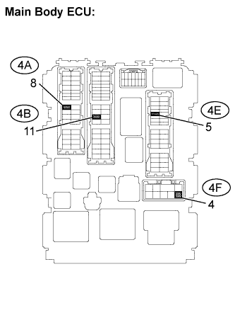
4B-11 - Body ground
| Ignition switch off
| Below 1 V
|
4F-4 - Body ground
|
4B-11 - Body ground
| Ignition switch ON
| 11 to 14 V
|
4F-4 - Body ground
|
ResultResult
| Proceed to
|
NG
| A
|
OK
| B
|
| 3.CHECK HARNESS AND CONNECTOR (MAIN BODY ECU - INTEGRATION RELAY) |
Remove the integration relay from the engine room relay block.
Disconnect the main body ECU connector.
Check the resistance.
- Standard resistance (Check for open):
Tester Connections
| Specified Conditions
|
1B-4 - 4F-4
| Below 1 Ω
|
1A-4 - 4B-11
|
- Standard resistance (Check for short):
Tester Connections
| Specified Conditions
|
4F-4 - Body ground
| 10 kΩ or higher
|
4B-11 - Body ground
|
Reinstall the integration relay.
Reconnect the main body ECU connector.
| | REPAIR OR REPLACE HARNESS OR CONNECTOR |
|
|
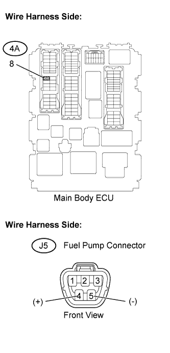
| 4.INSPECT MAIN BODY ECU (C/OPN RELAY) |
Remove the main body ECU.
Check the C/OPN relay resistance.
- Standard resistance:
Tester Connections
| Specified Conditions
|
4B-11 - 4A-8
| 10 kΩ or higher
|
Below 1 Ω
(when battery voltage is applied to terminals 4F-4 and 4E-5)
|
- HINT:
- Relay coil circuit between 4F-4 and 4E-5 is not through IGN fuse.
Reinstall the main body ECU.
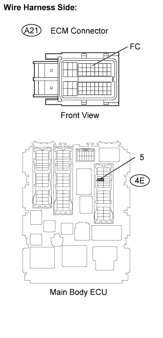
| 5.CHECK HARNESS AND CONNECTOR (MAIN BODY ECU - ECM) |
Disconnect the A21 ECM connector.
Disconnect the 4E connector from main body ECU.
Check the resistance.
- Standard resistance (Check for open):
Tester Connections
| Specified Conditions
|
Main Body ECU (4E-5) - FC (A21-7)
| Below 1 Ω
|
- Standard resistance (Check for short):
Tester Connections
| Specified Conditions
|
Main body ECU (4E-5) or FC (A21-7) - Body ground
| 10 kΩ or higher
|
Reconnect the main body ECU and the ECM connectors.
| | REPAIR OR REPLACE HARNESS OR CONNECTOR |
|
|
| 6.CHECK HARNESS AND CONNECTOR (C/OPN RELAY - FUEL PUMP - BODY GROUND) |
Check the harness and the connectors between the main body ECU and the fuel pump.
Disconnect the 4A main body ECU connector.
Disconnect the J5 fuel pump connector.
Check the resistance.
- Standard resistance (Check for open):
Tester Connections
| Specified Conditions
|
Main body ECU (4A-8) - Fuel pump (J5-4)
| Below 1 Ω
|
- Standard resistance (Check for short):
Tester Connections
| Specified Conditions
|
Main body ECU (4A-8) or Fuel pump (J5-4) - Body ground
| 10 kΩ or higher
|
Check the harness and the connectors between the fuel pump and the body ground.
Disconnect the J5 fuel pump connector.
Check the resistance.
- Standard resistance (Check for open):
Tester Connections
| Specified Conditions
|
Fuel pump (J5-5) - Body ground
| Below 1 Ω
|
Reconnect the main body ECU connector.
Reconnect the fuel pump connector.
| | REPAIR OR REPLACE HARNESS OR CONNECTOR |
|
|
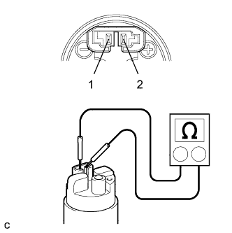
Inspect fuel pump resistance.
Measure the resistance between the terminals.
- Standard resistance:
- 0.2 to 3.0 Ω at 20°C (68°F)
Inspect fuel pump operation.
Apply the battery voltage to both the terminals. Check that the pump operates.
- NOTICE:
- These tests must be done quickly (within 10 seconds) to prevent the coil from burning out.
- Keep the fuel pump as far away from the battery as possible.
- Always switch at the battery side.
| 8.READ VALUE USING TECHSTREAM (STARTER SIGNAL) |
Connect the Techstream to the DLC3.
Turn the ignition switch to ON.
Turn the Techstream on.
Enter the following menus: Powertrain / Engine and ECT / Data List / Starter Signal.
Check the result when the ignition switch is turned to ON and START.
- OK:
Ignition Switch Position
| Starter Signal
|
ON
| Close (Starter signal OFF)
|
START
| Open (Starter signal ON)
|
| 9.READ VALUE USING TECHSTREAM (ENGINE SPEED) |
Connect the Techstream to the DLC3.
Turn the ignition switch to ON.
Turn the Techstream on.
Enter the following menus: Powertrain / Engine and ECT / Data List / Engine Speed.
Read the values displayed on the Techstream while cranking.
- OK:
- Values are displayed continuously.