Brake. Toyota Rav4. Aca30, 33, 38 Gsa33 Zsa30, 35
DESCRIPTION
WIRING DIAGRAM
INSPECTION PROCEDURE
CHECK HARNESS AND CONNECTOR (MOMENTARY INTERRUPTION)
REPAIR OR REPLACE HARNESS OR CONNECTOR (SKID CONTROL ECU - REAR SPEED SENSOR)
PERFORM TEST MODE (SIGNAL CHECK)
READ VALUE USING INTELLIGENT TESTER (RR/RL WHEEL SPEED)
PERFORM TEST MODE (SIGNAL CHECK)
CHECK SKID CONTROL SENSOR/REAR SPEED SENSOR INSTALLATION
CHECK REAR SPEED SENSOR TIP
CHECK REAR SPEED SENSOR ROTOR
INSPECT SKID CONTROL SENSOR/REAR SPEED SENSOR
CHECK HARNESS AND CONNECTOR (SKID CONTROL SENSOR WIRE)
CHECK HARNESS AND CONNECTOR (SKID CONTROL ECU - SKID CONTROL SENSOR/REAR SPEED SENSOR)
INSPECT SKID CONTROL ECU (SENSOR INPUT)
PERFORM TEST MODE (SIGNAL CHECK)
REPLACE REAR AXLE HUB AND BEARING ASSEMBLY
PERFORM TEST MODE (SIGNAL CHECK)
REPLACE REAR SPEED SENSOR
PERFORM TEST MODE (SIGNAL CHECK)
REPLACE REAR SPEED SENSOR ROTOR
PERFORM TEST MODE (SIGNAL CHECK)
DTC C1273 Low Output Signal of Rear Speed Sensor RH (Test Mode DTC) |
DTC C1274 Low Output Signal of Rear Speed Sensor LH (Test Mode DTC) |
DTC C1277 Abnormal Change in Output Signal of Rear Speed Sensor RH (Test Mode DTC) |
DTC C1278 Abnormal Change in Output Signal of Rear Speed Sensor LH (Test Mode DTC) |
DESCRIPTION
DTCs C1273 to C1278 will be cleared when the speed sensor sends a vehicle speed signal or when Test Mode ends. DTCs from C1273 to C1278 are output only in Test Mode.DTC Code
| DTC Detection Condition
| Trouble Area
|
C1273
C1274
| Detected only during Test Mode.
| - Rear speed sensor RH/LH
- Sensor installation
- Speed sensor rotor
|
C1277
C1278
| Detected only during Test Mode.
| Speed sensor rotor
|
- HINT:
- DTCs C1273 and C1277 are for the rear speed sensor RH.
- DTCs C1274 and C1278 are for the rear speed sensor LH.
WIRING DIAGRAM
Refer to DTCs C1403 and C1404 (RAV4_ACA30 RM00000369R00BX_02.html).
INSPECTION PROCEDURE
- NOTICE:
- When replacing the brake actuator assembly, perform zero point calibration (RAV4_ACA30 RM000001K1O00SX.html).
| 1.CHECK HARNESS AND CONNECTOR (MOMENTARY INTERRUPTION) |
Using the intelligent tester, check for any momentary interruption in the wire harness and connector corresponding to the DTC (RAV4_ACA30 RM000000XHS04QX.html).
ABS/VSC/TRC:Tester Display
| Measurement Item/Range
| Normal Condition
| Diagnostic Note
|
RR Speed Open
| RR speed sensor open detection / ERROR or NORMAL
| ERROR: Momentary interruption
NORMAL: Normal
| -
|
RL Speed Open
| RL speed sensor open detection / ERROR or NORMAL
| ERROR: Momentary interruption
NORMAL: Normal
| -
|
- Result:
Result
| Proceed to
|
There are momentary interruptions.
| A
|
There are no momentary interruptions.
| B
|
There is a constant open circuit.
| C
|
- HINT:
- Perform the above inspection before removing the sensor and connector.
| 2.REPAIR OR REPLACE HARNESS OR CONNECTOR (SKID CONTROL ECU - REAR SPEED SENSOR) |
Turn the ignition switch off.
Repair or replace the harness or connector.
Check for any momentary interruption between the skid control ECU and the rear speed sensor (RAV4_ACA30 RM000000XHS04QX.html).
Check that there are no momentary interruptions.
| 3.PERFORM TEST MODE (SIGNAL CHECK) |
Turn the ignition switch off.
Perform the sensor check in the Test Mode procedure (RAV4_ACA30 RM0000022CZ007X.html).
- OK:
- All Test Mode DTCs are cleared.
| 4.READ VALUE USING INTELLIGENT TESTER (RR/RL WHEEL SPEED) |
Turn the ignition switch off.
Connect the intelligent tester to the DLC3.
Start the engine.
Select the Data List mode on the intelligent tester (RAV4_ACA30 RM000000ONK01EX.html).
ABS/VSC/TRC:Tester Display
| Measurement Item/Range
| Normal Condition
| Diagnostic Note
|
RR Wheel Speed
| RR wheel speed sensor reading / min.: 0 km/h (0 mph), max.: 326.4 km/h (202.8 mph)
| Actual wheel speed
| Similar to speed indicated on the speedometer.
|
RL Wheel Speed
| RL wheel speed sensor reading / min.: 0 km/h (0 mph), max.: 326.4 km/h (202.8 mph)
| Actual wheel speed
| Similar to speed indicated on the speedometer.
|
Check that there is no difference between the speed value output from the speed sensor displayed on the intelligent tester and the speed value displayed on the speedometer when driving the vehicle.
- HINT:
- Factors that affect the indicated vehicle speed include tire size, tire inflation, and tire wear. The speed indicated on the speedometer has an allowable margin of error. This can be tested using a speedometer tester (calibrated chassis dynamometer). For details about testing and the margin of error, see the reference chart (RAV4_ACA30 RM0000020M9001X.html).
- OK:
- The speed value output from the speed sensor displayed on the intelligent tester is the same as the actual vehicle speed measured using a speedometer tester (calibrated chassis dynamometer).
| 5.PERFORM TEST MODE (SIGNAL CHECK) |
Turn the ignition switch off.
Perform the sensor check in the Test Mode procedure (RAV4_ACA30 RM0000022CZ007X.html).
- OK:
- All Test Mode DTCs are cleared.
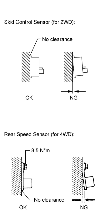
| 6.CHECK SKID CONTROL SENSOR/REAR SPEED SENSOR INSTALLATION |
Turn the ignition switch off.
for 2WD:
Check the skid control sensor installation.
- OK:
- There is no clearance between the sensor and the rear axle carrier.
for 4WD:
Check the rear speed sensor installation.
- OK:
- There is no clearance between the sensor and the rear axle carrier.
- The installation bolt is tightened properly.
- Torque:
- 8.5 N*m (87 kgf*cm, 75 in.*lbf)
- Result:
Result
| Proceed to
|
OK
| for 4WD
| A
|
for 2WD
| B
|
NG
| for 2WD
| C
|
for 4WD
| D
|
| 7.CHECK REAR SPEED SENSOR TIP |
Remove the rear speed sensor (RAV4_ACA30 RM000001XVL007X.html).
Check the speed sensor tip.
- OK:
- No scratches, oil, or foreign matter on the sensor tip.
- NOTICE:
- Check the speed sensor signal after cleaning or replacement (RAV4_ACA30 RM0000022CZ007X.html).
| | CLEAN OR REPLACE REAR SPEED SENSOR |
|
|
| 8.CHECK REAR SPEED SENSOR ROTOR |
Remove the rear axle hub and bearing assembly (RAV4_ACA30 RM00000227S005X.html).
Check the speed sensor rotor.
- OK:
- No scratches, oil, or foreign matter on the rotors.
- NOTICE:
- Check the speed sensor signal after cleaning or replacement (RAV4_ACA30 RM0000022CZ007X.html).
- HINT:
- If the rear speed sensor rotor needs to be replaced, replace it together with the rear axle hub and bearing assembly.
| | CLEAN OR REPLACE REAR SPEED SENSOR ROTOR |
|
|
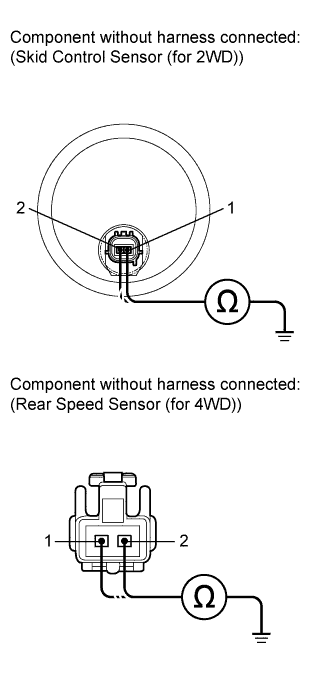
| 9.INSPECT SKID CONTROL SENSOR/REAR SPEED SENSOR |
for 4WD:
Install the rear speed sensor and rear speed sensor rotor.
Make sure that there is no looseness in the locking part and connecting part of the connector.
Disconnect the sensor connector.
Measure the resistance according to the value(s) in the table below.
- Standard Resistance:
Tester Connection
| Condition
| Specified Condition
|
1 - Body ground
| Always
| 10 kΩ or higher
|
2 - Body ground
| Always
| 10 kΩ or higher
|
- Result:
Result
| Proceed to
|
OK
| for 2WD
| A
|
for 4WD
| B
|
NG
| for 2WD
| C
|
for 4WD
| D
|
- NOTICE:
- Check the speed sensor signal after replacement (RAV4_ACA30 RM0000022CZ007X.html).
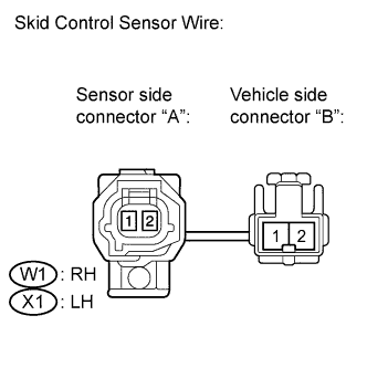
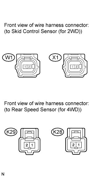
| 10.CHECK HARNESS AND CONNECTOR (SKID CONTROL SENSOR WIRE) |
Make sure that there is no looseness in the locking part and connecting part of the connectors.
Disconnect the skid control sensor wire.
Measure the resistance according to the value(s) in the table below.
- Standard Resistance:
- for RH:
Tester Connection
| Condition
| Specified Condition
|
W1 ("A"-2) - W1 ("B"-1)
| Always
| Below 1 Ω
|
W1 ("A"-2) - W1 ("B"-2)
| Always
| 10 kΩ or higher
|
W1 ("A"-2) - Body ground
| Always
| 10 kΩ or higher
|
W1 ("A"-1) - W1 ("B"-2)
| Always
| Below 1 Ω
|
W1 ("A"-1) - W1 ("B"-1)
| Always
| 10 kΩ or higher
|
W1 ("A"-1) - Body ground
| Always
| 10 kΩ or higher
|
- for LH:
Tester Connection
| Condition
| Specified Condition
|
X1 ("A"-2) - X1 ("B"-1)
| Always
| Below 1 Ω
|
X1 ("A"-2) - X1 ("B"-2)
| Always
| 10 kΩ or higher
|
X1 ("A"-2) - Body ground
| Always
| 10 kΩ or higher
|
X1 ("A"-1) - X1 ("B"-2)
| Always
| Below 1 Ω
|
X1 ("A"-1) - X1 ("B"-1)
| Always
| 10 kΩ or higher
|
X1 ("A"-1) - Body ground
| Always
| 10 kΩ or higher
|
- NOTICE:
- Check the speed sensor signal after replacement (RAV4_ACA30 RM0000022CZ007X.html).
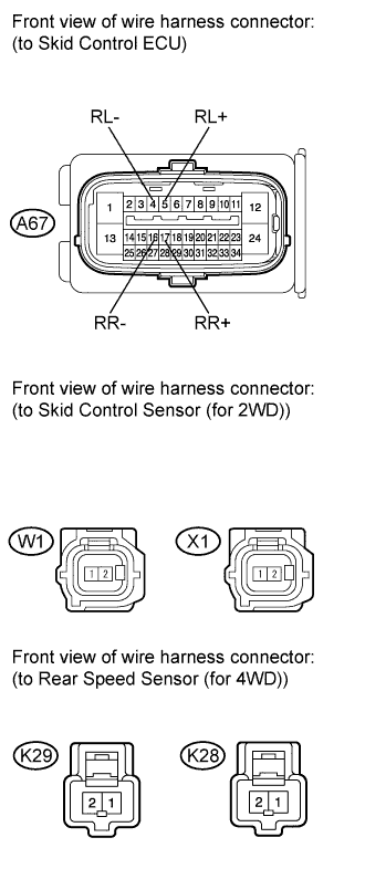
| 11.CHECK HARNESS AND CONNECTOR (SKID CONTROL ECU - SKID CONTROL SENSOR/REAR SPEED SENSOR) |
for 2WD:
Reconnect the skid control sensor wire.
Make sure that there is no looseness in the locking part and connecting part of the connector.
Disconnect the skid control ECU connector.
Measure the resistance according to the value(s) in the table below.
- Standard Resistance:
- for 2WD RH:
Tester Connection
| Condition
| Specified Condition
|
A67-17 (RR+) - W1-2
| Always
| Below 1 Ω
|
A67-17 (RR+) - Body ground
| Always
| 10 kΩ or higher
|
A67-16 (RR-) - W1-1
| Always
| Below 1 Ω
|
A67-16 (RR-) - Body ground
| Always
| 10 kΩ or higher
|
- for 4WD RH:
Tester Connection
| Condition
| Specified Condition
|
A67-17 (RR+) - K29-1
| Always
| Below 1 Ω
|
A67-17 (RR+) - Body ground
| Always
| 10 kΩ or higher
|
A67-16 (RR-) - K29-2
| Always
| Below 1 Ω
|
A67-16 (RR-) - Body ground
| Always
| 10 kΩ or higher
|
- for 2WD LH:
Tester Connection
| Condition
| Specified Condition
|
A67-5 (RL+) - X1-2
| Always
| Below 1 Ω
|
A67-5 (RL+) - Body ground
| Always
| 10 kΩ or higher
|
A67-4 (RL-) - X1-1
| Always
| Below 1 Ω
|
A67-4 (RL-) - Body ground
| Always
| 10 kΩ or higher
|
- for 4WD LH:
Tester Connection
| Condition
| Specified Condition
|
A67-5 (RL+) - K28-1
| Always
| Below 1 Ω
|
A67-5 (RL+) - Body ground
| Always
| 10 kΩ or higher
|
A67-4 (RL-) - K28-2
| Always
| Below 1 Ω
|
A67-4 (RL-) - Body ground
| Always
| 10 kΩ or higher
|
| | REPAIR OR REPLACE HARNESS OR CONNECTOR |
|
|
| 12.INSPECT SKID CONTROL ECU (SENSOR INPUT) |
Reconnect the skid control ECU connector.
Turn the ignition switch to ON.
Measure the voltage according to the value(s) in the table below.
- Standard Voltage:
- for 2WD RH:
Tester Connection
| Switch Condition
| Specified Condition
|
W1-2 - Body ground
| Ignition switch ON
| 8 to 14 V
|
- for 4WD RH:
Tester Connection
| Switch Condition
| Specified Condition
|
K29-1 - Body ground
| Ignition switch ON
| 8 to 14 V
|
- for 2WD LH:
Tester Connection
| Switch Condition
| Specified Condition
|
X1-2 - Body ground
| Ignition switch ON
| 8 to 14 V
|
- for 4WD LH:
Tester Connection
| Switch Condition
| Specified Condition
|
K28-1 - Body ground
| Ignition switch ON
| 8 to 14 V
|
| 13.PERFORM TEST MODE (SIGNAL CHECK) |
Turn the ignition switch off.
Perform the sensor check in the Test Mode procedure (RAV4_ACA30 RM0000022CZ007X.html).
- OK:
- All Test Mode DTCs are cleared.
- Result:
Result
| Proceed to
|
OK
| A
|
NG
| for 2WD
| B
|
for 4WD
| C
|
| 14.REPLACE REAR AXLE HUB AND BEARING ASSEMBLY |
Turn the ignition switch off.
Replace the rear axle hub and bearing assembly (rear speed sensor and rotor) (RAV4_ACA30 RM00000227S005X.html).
- HINT:
- The rear speed sensor rotor is incorporated into the rear axle hub and bearing assembly.
- If the rear speed sensor rotor needs to be replaced, replace it together with the rear axle hub and bearing assembly with rear speed sensor.
- NOTICE:
- Check the speed sensor signal after replacement (RAV4_ACA30 RM0000022CZ007X.html).
| 15.PERFORM TEST MODE (SIGNAL CHECK) |
Perform the sensor check in the Test Mode procedure (RAV4_ACA30 RM0000022CZ007X.html).
- OK:
- All Test Mode DTCs are cleared.
| 16.REPLACE REAR SPEED SENSOR |
Turn the ignition switch off.
Replace the rear speed sensor (RAV4_ACA30 RM000001XVL007X.html).
- NOTICE:
- Check the speed sensor signal after replacement (RAV4_ACA30 RM0000022CZ007X.html).
| 17.PERFORM TEST MODE (SIGNAL CHECK) |
Perform the sensor check in the Test Mode procedure (RAV4_ACA30 RM0000022CZ007X.html).
- OK:
- All Test Mode DTCs are cleared.
| 18.REPLACE REAR SPEED SENSOR ROTOR |
Turn the ignition switch off.
Replace the rear axle hub and bearing assembly (rear speed sensor rotor) (RAV4_ACA30 RM00000227S005X.html).
- HINT:
- If the rear speed sensor rotor needs to be replaced, replace it together with the rear axle hub and bearing assembly.
- NOTICE:
- Check the speed sensor signal after replacement (RAV4_ACA30 RM0000022CZ007X.html).
| 19.PERFORM TEST MODE (SIGNAL CHECK) |
Perform the sensor check in the Test Mode procedure (RAV4_ACA30 RM0000022CZ007X.html).
- OK:
- All Test Mode DTCs are cleared.