Dtc C1380 Stop Light Control Relay Malfunction
Brake. Toyota Rav4. Aca30, 33, 38 Gsa33 Zsa30, 35
DESCRIPTION
WIRING DIAGRAM
INSPECTION PROCEDURE
CHECK STOP LIGHT OPERATION
READ VALUE USING INTELLIGENT TESTER (STOP LIGHT SWITCH)
INSPECT SKID CONTROL ECU (STP TERMINAL)
PERFORM ACTIVE TEST USING INTELLIGENT TESTER (STOP LIGHT RELAY)
RECONFIRM DTC
INSPECT STOP LIGHT CONTROL RELAY (BRK)
INSPECT ENGINE ROOM NO. 1 RELAY BLOCK (POWER SOURCE TERMINAL)
INSPECT SKID CONTROL ECU (STPO TERMINAL)
INSPECT SKID CONTROL ECU (STP2 TERMINAL)
DTC C1380 Stop Light Control Relay Malfunction |
DESCRIPTION
Upon receiving the downhill assist control or hill-start assist control operating signal from the skid control ECU, the relay contact turns on and the stop light comes on.DTC Code
| DTC Detection Condition
| Trouble Area
|
C1380
| Either of the following is detected:
- When the voltage at the IG1 terminal is between 10 and 14 V and the stop light control relay drive output (STPO) is on, a signal has not been input to the STP terminal for 5 seconds or more.
- When the voltage at the IG1 terminal is between 10 and 14 V and the stop light control relay drive output (STPO) is off, the signal at the STP is different from the input signal at the STP2 for 5 seconds or more.
| - STOP fuse
- Stop light switch circuit
- Stop light control relay
- Stop light control relay (BRK)
- Stop light control relay circuit
- Brake actuator assembly (Skid control ECU)
|
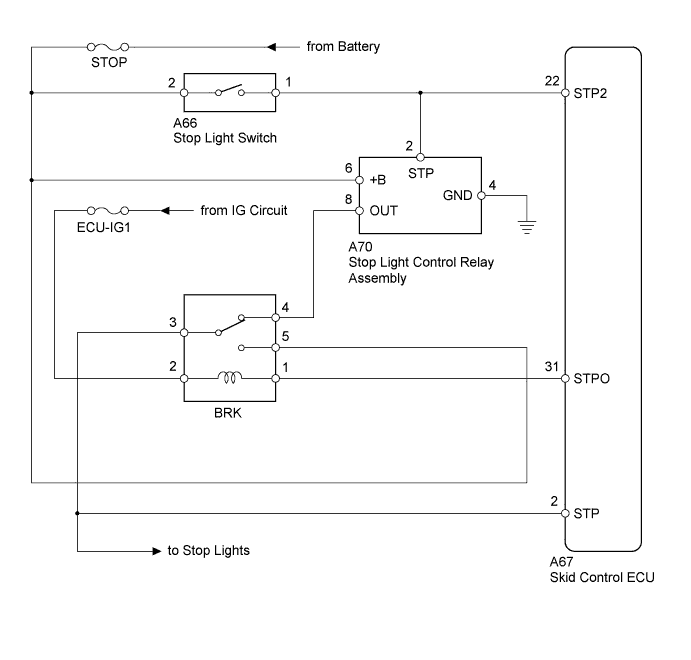
WIRING DIAGRAM
INSPECTION PROCEDURE
- NOTICE:
- When replacing the brake actuator assembly, perform zero point calibration (RAV4_ACA30 RM000001K1O00SX.html).
- Inspect the fuses for circuits related to this system before performing the following inspection procedure.
- HINT:
- When C1425 is output together with C1380, inspect and repair the trouble areas indicated by C1425 first (RAV4_ACA30 RM000000XIE04TX.html).
| 1.CHECK STOP LIGHT OPERATION |
Check that the stop lights come on when the brake pedal is depressed, and go off when the brake pedal is released.
- OK:
Condition
| Illumination Condition
|
Brake pedal depressed.
| ON
|
Brake pedal released.
| OFF
|
| 2.READ VALUE USING INTELLIGENT TESTER (STOP LIGHT SWITCH) |
Connect the intelligent tester to the DLC3.
Turn the ignition switch to ON.
Select the Data List mode on the intelligent tester (RAV4_ACA30 RM000000ONK01EX.html).
ABS/VSC/TRC:Tester Display
| Measurement Item/Range
| Normal Condition
| Diagnostic Note
|
Stop Light SW
| Stop light switch / ON or OFF
| ON: Brake pedal depressed
OFF: Brake pedal released
| -
|
Check that the stop light switch condition observed on the intelligent tester changes according to brake pedal operation.
- OK:
- The intelligent tester displays ON or OFF according to brake pedal operation.
| 3.INSPECT SKID CONTROL ECU (STP TERMINAL) |
Turn the ignition switch off.
Make sure that there is no looseness in the locking part and connecting part of the connector.
Disconnect the skid control ECU connector.
Measure the voltage according to the value(s) in the table below.
- Standard Voltage:
Tester Connection
| Switch Condition
| Specified Condition
|
A67-2 (STP) - Body ground
| Stop light switch off
(Brake pedal released)
| Below 1.5 V
|
Stop light switch on
(Brake pedal depressed)
| 8 to 14 V
|
| | REPAIR OR REPLACE HARNESS OR CONNECTOR (STP CIRCUIT) |
|
|
| 4.PERFORM ACTIVE TEST USING INTELLIGENT TESTER (STOP LIGHT RELAY) |
Reconnect the skid control ECU connector.
Connect the intelligent tester to the DLC3.
Start the engine.
Select the Active Test mode on the intelligent tester (RAV4_ACA30 RM000000ONK01EX.html).
ABS/VSC/TRC:Tester Display
| Test Part
| Control Range
| Diagnostic Note
|
Stop Light Relay
| Stop light control relay (BRK)
| Relay ON / OFF
| Observe the stop lights.
|
Check that the "ON" and "OFF" of the stop lights can be shown on the rear combination light by the intelligent tester.
- OK:
- The stop lights turn on or off in accordance with the intelligent tester.
Turn the ignition switch off.
Clear the DTCs (RAV4_ACA30 RM000000ONJ027X.html).
Start the engine.
Perform a road test.
Check if the same DTC is output (RAV4_ACA30 RM000000ONJ027X.html).
- Result:
Result
| Proceed to
|
DTC (C1380) is not output.
| A
|
DTC (C1380) is output.
| B
|
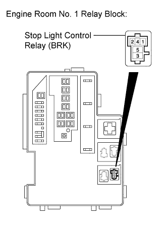
| 6.INSPECT STOP LIGHT CONTROL RELAY (BRK) |
Turn the ignition switch off.
Remove the stop light control relay (BRK).
Measure the resistance according to the value(s) in the table below.
- Standard Resistance:
Tester Connection
| Condition
| Specified Condition
|
3 - 4
| Voltage is not applied between terminals 1 and 2
| Below 1 Ω
|
3 - 5
| Voltage is not applied between terminals 1 and 2
| 10 kΩ or higher
|
3 - 4
| Voltage is applied between terminals 1 and 2
| 10 kΩ or higher
|
3 - 5
| Voltage is applied between terminals 1 and 2
| Below 1 Ω
|
| | REPLACE STOP LIGHT CONTROL RELAY (BRK) |
|
|
| 7.INSPECT ENGINE ROOM NO. 1 RELAY BLOCK (POWER SOURCE TERMINAL) |
Measure the voltage according to the value(s) in the table below.
- Standard Voltage:
Tester Connection
| Switch Condition
| Specified Condition
|
Stop light control relay (BRK) terminal 5 - Body ground
| Always
| 11 to 14 V
|
Stop light control relay (BRK) terminal 2 - Body ground
| Ignition switch ON
| 11 to 14 V
|
| | REPAIR OR REPLACE HARNESS OR CONNECTOR (POWER SOURCE CIRCUIT) |
|
|
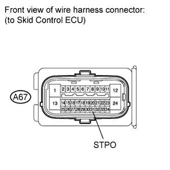
| 8.INSPECT SKID CONTROL ECU (STPO TERMINAL) |
Install the stop light control relay (BRK).
Make sure that there is no looseness in the locking part and connecting part of the connector.
Disconnect the skid control ECU connector.
Turn the ignition switch to ON.
Measure the voltage according to the value(s) in the table below.
- Standard Voltage:
Tester Connection
| Switch Condition
| Specified Condition
|
A67-31 (STPO) - Body ground
| Ignition switch ON
| 11 to 14 V
|
| | REPAIR OR REPLACE HARNESS OR CONNECTOR (STPO CIRCUIT) |
|
|
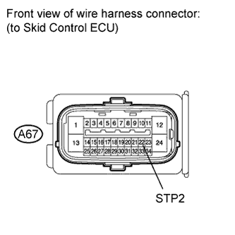
| 9.INSPECT SKID CONTROL ECU (STP2 TERMINAL) |
Turn the ignition switch off.
Make sure that there is no looseness in the locking part and connecting part of the connector.
Disconnect the skid control ECU connector.
Measure the voltage according to the value(s) in the table below.
- Standard Voltage:
Tester Connection
| Switch Condition
| Specified Condition
|
A67-22 (STP2) - Body ground
| Stop light switch on (Brake pedal depressed)
| 8 to 14 V
|
Stop light switch off (Brake pedal released)
| Below 1.5 V
|
| | REPAIR OR REPLACE HARNESS OR CONNECTOR (STP2 CIRCUIT) |
|
|