Brake. Toyota Rav4. Aca30, 33, 38 Gsa33 Zsa30, 35
DESCRIPTION
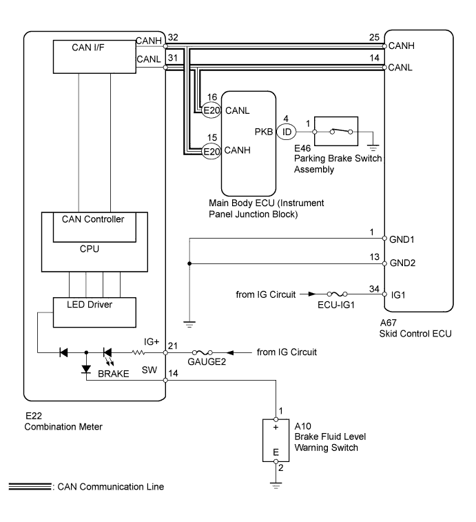
WIRING DIAGRAM
INSPECTION PROCEDURE
PREPARE FOR INSPECTION
CHECK DTC FOR ABS
CHECK CAN COMMUNICATION SYSTEM
INSPECT SKID CONTROL ECU CONNECTOR
CHECK HARNESS AND CONNECTOR (SKID CONTROL ECU - BATTERY AND BODY GROUND)
READ VALUE USING INTELLIGENT TESTER (PARKING BRAKE SWITCH)
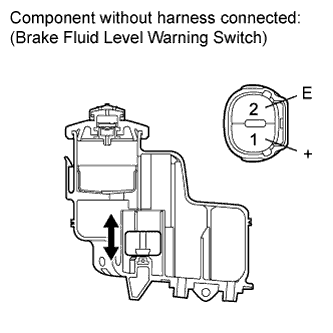
INSPECT BRAKE FLUID LEVEL WARNING SWITCH
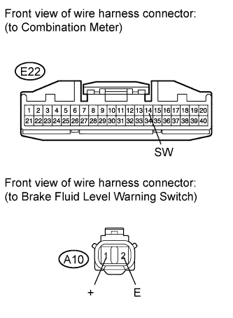
CHECK HARNESS AND CONNECTOR (BRAKE FLUID LEVEL WARNING SW - COMBINATION METER/BODY GROUND)
INSPECT COMBINATION METER ASSEMBLY
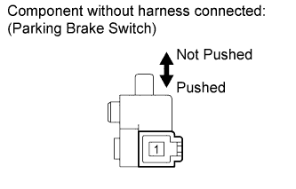
INSPECT PARKING BRAKE SWITCH ASSEMBLY
CHECK HARNESS AND CONNECTOR (PARKING BRAKE SWITCH - JUNCTION BLOCK/BODY GROUND)
VEHICLE STABILITY CONTROL SYSTEM - Brake Warning Light Remains ON |
DESCRIPTION
If any of the following conditions are detected, the brake warning light remains on:- The ECU connectors are disconnected from the skid control ECU.
- The brake fluid level is insufficient.
- The parking brake is applied.
- The EBD is defective.
WIRING DIAGRAM
INSPECTION PROCEDURE
- NOTICE:
- When replacing the brake actuator assembly, perform zero point calibration (RAV4_ACA30 RM000001K1O00SX.html).
Check that both of the following conditions are satisfied.
- The brake fluid level in the brake master cylinder reservoir is correct.
- The parking brake is released.
- HINT:
- When the ABS warning light remains illuminated, repair the malfunctions in the ABS system first.
Check if any ABS DTCs are output (RAV4_ACA30 RM000000ONJ02VX.html).
- Result:
Result
| Proceed to
|
DTC is not output.
| A
|
DTC is output.
| B
|
| 3.CHECK CAN COMMUNICATION SYSTEM |
Check if a CAN communication system DTC is output (RAV4_ACA30 RM000001W16007X.html).
- Result:
Result
| Proceed to
|
DTC is not output.
| A
|
DTC is output.
| B
|
| 4.INSPECT SKID CONTROL ECU CONNECTOR |
Check if the skid control ECU connector is properly installed.
- OK:
- The skid control ECU connector is properly installed.
| | CONNECT CONNECTOR TO ECU SECURELY |
|
|
| 5.CHECK HARNESS AND CONNECTOR (SKID CONTROL ECU - BATTERY AND BODY GROUND) |
Disconnect the skid control ECU connector.
Measure the resistance according to the value(s) in the table below.
- Standard Resistance:
Tester Connection
| Condition
| Specified Condition
|
A67-1 (GND1) - Body ground
| Always
| Below 1 Ω
|
A67-13 (GND2) - Body ground
| Always
| Below 1 Ω
|
Measure the voltage according to the value(s) in the table below.
- Standard Voltage:
Tester Connection
| Switch Condition
| Specified Condition
|
A67-34 (IG1) - Body ground
| Ignition switch ON
| 11 to 14 V
|
| | REPAIR OR REPLACE HARNESS OR CONNECTOR |
|
|
| 6.READ VALUE USING INTELLIGENT TESTER (PARKING BRAKE SWITCH) |
Using the Data List, check for proper functioning of the parking brake switch.
ABS/VSC/TRC:Tester Display
| Measurement Item/Range
| Normal Condition
| Diagnostic Note
|
Parking Brake SW
| Parking brake switch / ON or OFF
| ON: Parking brake applied
OFF: Parking brake released
| -
|
- OK:
- When the parking brake lever is operated, the display changes as shown above.
| 7.INSPECT BRAKE FLUID LEVEL WARNING SWITCH |
Remove the reservoir tank cap and strainer.
Disconnect the brake fluid level warning switch connector.
Measure the resistance according to the value(s) in the table below.
- HINT:
- A float is placed inside the reservoir. Its position can be changed by increasing or decreasing the brake fluid level.
- Standard Resistance:
Tester Connection
| Condition
| Specified Condition
|
1 (+) - 2 (E)
| Float up (Switch off)
| 10 kΩ or higher
|
1 (+) - 2 (E)
| Float down (Switch on)
| Below 1 Ω
|
- Result:
Result
| Proceed to
|
OK
| A
|
NG
| for LHD
| B
|
for RHD
| C
|
- HINT:
- If there is no problem after the above check is finished, adjust the brake fluid level to the MAX level.
| 8.CHECK HARNESS AND CONNECTOR (BRAKE FLUID LEVEL WARNING SW - COMBINATION METER/BODY GROUND) |
Disconnect the combination meter connector.
Disconnect the brake fluid level warning switch connector.
Measure the resistance according to the value(s) in the table below.
- Standard Resistance:
Tester Connection
| Condition
| Specified Condition
|
E22-14 (SW) - A10-1 (+)
| Always
| Below 1 Ω
|
E22-14 (SW) - Body ground
| Always
| 10 kΩ or higher
|
A10-2 (E) - Body ground
| Always
| Below 1 Ω
|
| | REPAIR OR REPLACE HARNESS OR CONNECTOR |
|
|
| 9.INSPECT COMBINATION METER ASSEMBLY |
Inspect the combination meter (RAV4_ACA30 RM0000020M0001X.html).
| 10.INSPECT PARKING BRAKE SWITCH ASSEMBLY |
Remove the parking brake switch (RAV4_ACA30 RM000001C4T019X.html).
Measure the resistance according to the value(s) in the table below.
- Standard Resistance:
Tester Connection
| Switch Condition
| Specified Condition
|
1 - Body ground
| Parking brake switch on
(Switch pin not pushed)
| Below 1 Ω
|
Parking brake switch off
(Switch pin pushed)
| 10 kΩ or higher
|
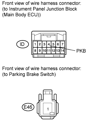
| 11.CHECK HARNESS AND CONNECTOR (PARKING BRAKE SWITCH - JUNCTION BLOCK/BODY GROUND) |
Disconnect the junction block connector.
Disconnect the parking brake switch connector.
Measure the resistance according to the value(s) in the table below.
- Standard Resistance:
Tester Connection
| Condition
| Specified Condition
|
ID-4 (PKB) - E46-1
| Always
| Below 1 Ω
|
ID-4 (PKB) - Body ground
| Always
| 10 kΩ or higher
|
| | REPAIR OR REPLACE HARNESS OR CONNECTOR |
|
|
| OK |
|
|
|
| REPLACE INSTRUMENT PANEL JUNCTION BLOCK |
|