Sfi System Fuel Injector Circuit
DESCRIPTION
WIRING DIAGRAM
INSPECTION PROCEDURE
CHECK FUEL INJECTOR ASSEMBLY (POWER SOURCE)
INSPECT FUEL INJECTOR ASSEMBLY
CHECK HARNESS AND CONNECTOR (FUEL INJECTOR ASSEMBLY - ECM)
CHECK HARNESS AND CONNECTOR (IGNITION SWITCH ASSEMBLY - FUEL INJECTOR ASSEMBLY)
SFI SYSTEM - Fuel Injector Circuit |
DESCRIPTION
The fuel injectors are located on the intake manifold. They inject fuel into the cylinders based on the signals from the ECM.
WIRING DIAGRAM
Refer to DTC P0201 (HILUX_TGN26 RM0000033OD00KX_02.html).
INSPECTION PROCEDURE
- NOTICE:
- Inspect the fuses for circuits related to this system before performing the following inspection procedure.
| 1.CHECK FUEL INJECTOR ASSEMBLY (POWER SOURCE) |
Disconnect the fuel injector assembly connectors.
Measure the voltage according to the value(s) in the table below.
- Standard Voltage:
Tester Connection
| Switch Condition
| Specified Condition
|
C65-1 - Body ground
| Ignition switch ON
| 11 to 14 V
|
C2-1 - Body ground
| Ignition switch ON
| 11 to 14 V
|
C66-1 - Body ground
| Ignition switch ON
| 11 to 14 V
|
C4-1 - Body ground
| Ignition switch ON
| 11 to 14 V
|
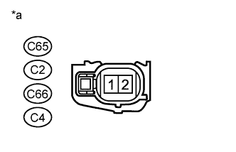
Text in Illustration*a
| Front view of wire harness connector
(to Fuel Injector Assembly)
|
Turn the ignition switch off.
Reconnect the fuel injector assembly connectors.
| 2.INSPECT FUEL INJECTOR ASSEMBLY |
Inspect the fuel injector assembly (HILUX_TGN26 RM000000YL901AX.html).
| 3.CHECK HARNESS AND CONNECTOR (FUEL INJECTOR ASSEMBLY - ECM) |
Disconnect the fuel injector assembly connectors.
Disconnect the ECM connector.
Measure the resistance according to the value(s) in the table below.
- Standard Resistance (Check for Open):
Tester Connection
| Condition
| Specified Condition
|
C65-2 - C98-6 (#10)
| Always
| Below 1 Ω
|
C2-2 - C98-7 (#20)
| Always
| Below 1 Ω
|
C66-2 - C98-8 (#30)
| Always
| Below 1 Ω
|
C4-2 - C98-9 (#40)
| Always
| Below 1 Ω
|
- Standard Resistance (Check for Short):
Tester Connection
| Condition
| Specified Condition
|
C65-2 or C98-6 (#10) - Body ground
| Always
| 10 kΩ or higher
|
C2-2 or C98-7 (#20) - Body ground
| Always
| 10 kΩ or higher
|
C66-2 or C98-8 (#30) - Body ground
| Always
| 10 kΩ or higher
|
C4-2 or C98-9 (#40) - Body ground
| Always
| 10 kΩ or higher
|
Reconnect the fuel injector assembly connectors.
Reconnect the ECM connector.
| | REPAIR OR REPLACE HARNESS OR CONNECTOR |
|
|
| 4.CHECK HARNESS AND CONNECTOR (IGNITION SWITCH ASSEMBLY - FUEL INJECTOR ASSEMBLY) |
Disconnect the fuel injector assembly connectors.
Disconnect the ignition switch connector.
Measure the resistance according to the value(s) in the table below.
- Standard Resistance (Check for Open):
Tester Connection
| Condition
| Specified Condition
|
C65-1 - G9-6 (IG2)
| Always
| Below 1 Ω
|
C2-1 - G9-6 (IG2)
| Always
| Below 1 Ω
|
C66-1 - G9-6 (IG2)
| Always
| Below 1 Ω
|
C4-1 - G9-6 (IG2)
| Always
| Below 1 Ω
|
- Standard Resistance (Check for Short):
Tester Connection
| Condition
| Specified Condition
|
C65-1 or G9-6 (IG2) - Body ground
| Always
| 10 kΩ or higher
|
C2-1 or G9-6 (IG2) - Body ground
| Always
| 10 kΩ or higher
|
C66-1 or G9-6 (IG2) - Body ground
| Always
| 10 kΩ or higher
|
C4-1 or G9-6 (IG2) - Body ground
| Always
| 10 kΩ or higher
|
Reconnect the fuel injector connector.
Reconnect the ignition switch connector.
| | REPAIR OR REPLACE HARNESS OR CONNECTOR |
|
|