Головка Блока Цилиндров - Узлы И Детали
Land Cruiser Prado GRJ150 TRJ150 TRJ155 KDJ150 TRJ155 LJ150 - МЕХАНИЧЕСКАЯ ЧАСТЬ ДВИГАТЕЛЯ 5L-E
ГОЛОВКА БЛОКА ЦИЛИНДРОВ - УЗЛЫ И ДЕТАЛИ
1 / 1
| 1. INSTALL ENGINE OIL PRESSURE SWITCH ASSEMBLY |
Clean the threads of the oil pressure switch and apply adhesive to them.
Using a 24 mm deep socket wrench, install the oil pressure switch.
| 2. INSTALL OIL FILTER BRACKET SUB-ASSEMBLY |
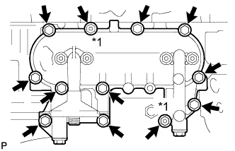
Install a new gasket and the oil filter bracket with the 10 bolts and 2 nuts.
| *1 | Nut |
| 3. INSTALL EXHAUST MANIFOLD |

Установите новую прокладку на головку блока цилиндров.
| *a | Метка внешней стороны |

Установите выпускной коллектор и закрепите его 6 болтами и 2 новыми гайками. Равномерно, в несколько этапов затяните болты и гайки.
| *1 | Гайка |
| 4. INSTALL NO. 1 EXHAUST MANIFOLD HEAT INSULATOR |

Установите теплозащитный экран и закрепите его 3 болтами.
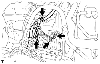
| 5. INSTALL VACUUM PUMP OIL OUTLET HOSE |

Install the vacuum pump oil outlet hose with the bolt and 2 new gaskets.
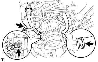
| 6. INSTALL UNION |
Clean the threads of the union and apply adhesive to them.
Install the union to the cylinder block.
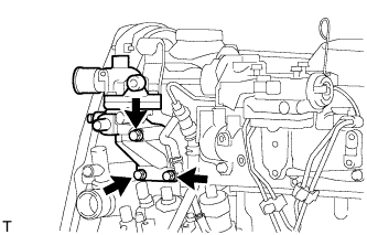
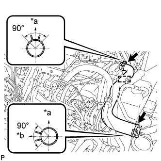
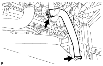
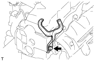
| 7. INSTALL VACUUM PUMP OIL INLET HOSE |

Connect the vacuum pump oil inlet hose with a new gasket and the union bolt.
| *1 | Stopper-bar |
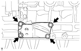
| 8. INSTALL NO. 1 FRONT ENGINE MOUNTING BRACKET RH |
Install the engine mounting bracket with the 4 bolts.
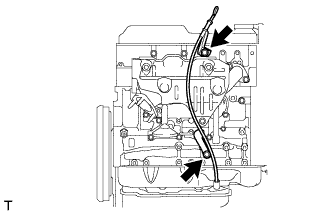
| 9. INSTALL ENGINE OIL LEVEL DIPSTICK GUIDE |
Apply a light coat of engine oil to a new O-ring.
Install the O-ring to the dipstick guide.
Install the dipstick guide with the 2 bolts.
Install the dipstick.
| 10. INSTALL NO. 1 FRONT ENGINE MOUNTING BRACKET LH |
Install the engine mounting bracket with the 4 bolts.
| 11. INSTALL PUMP BRACKET |
Install the pump bracket with the 3 bolts.
| 12. INSTALL NO. 1 GENERATOR BRACKET |
Install the generator bracket with the 3 bolts.
| 13. INSTALL WATER BY-PASS HOSE UNION |
Clean the threads of the water by-pass hose union and apply adhesive to them.
Install the water by-pass hose union.
| 14. INSTALL INTAKE MANIFOLD |

Install a new gasket to the cylinder head with the protrusion facing upward.
| *a | Protrusion |
| *b | Upward |

Install the intake manifold with the 6 bolts and 2 nuts. Uniformly tighten the bolts and nuts in several steps.
| *1 | Nut |
Install the wire harness bracket with the bolt.
| 15. INSTALL WATER OUTLET HOUSING |
Install a new gasket to the cylinder head.
Install the outlet hosing with the 3 bolts
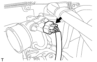
| 16. INSTALL ENGINE COOLANT TEMPERATURE SENSOR |
Install a new gasket and the engine coolant temperature sensor with the bolt.
Connect the engine coolant temperature sensor connector.
| 17. INSTALL CRANKSHAFT POSITION SENSOR |
Apply a light coat of engine oil to the O-ring of the crankshaft position sensor.
Install the crankshaft position sensor with the bolt.
Connect the crankshaft position sensor connector.
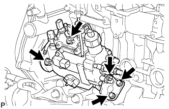
| 18. INSTALL INJECTION PUMP ASSEMBLY |
Temporarily install the injection pump to the timing gear case with the 2 nuts.
Temporarily install the injection pump stay to the injection pump rear end with the 3 bolts.

Rotate the pump body to align the marks on the pump flange and timing gear case.
Tighten the 2 nuts.
Tighten the 3 bolts.

Connect the 3 fuel hoses.
Connect the 5 connectors and attach the wire harness clamp.
| 19. INSTALL INJECTION PUMP DRIVE PULLEY |
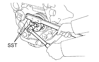
Using SST, install the injection pump drive pulley with the nut.
| 20. INSTALL GLOW PLUG ASSEMBLY |
Using a 12 mm deep socket wrench, install the 4 glow plugs.
| 21. INSTALL NOZZLE HOLDER & NOZZLE SET |
Install 4 new injection nozzle seat gaskets and the 4 injection nozzle seats to the injection nozzle holes of the cylinder head.
Using SST, install the 4 nozzle holder and nozzle sets.
| 22. INSTALL NOZZLE LEAKAGE PIPE ASSEMBLY |
Install 4 new ring packing washers and the leakage pipe with the 4 nuts.
Connect the fuel hose to the leakage pipe.
| 23. INSTALL NO. 1 GLOW PLUG CONNECTOR |
Install the No. 1 glow plug resistor insulator and No. 1 glow plug connector.

Install the glow plug connector with the 4 nuts. Uniformly tighten the nuts.
| *1 | Nut |
| *2 | Washer |
| *3 | No. 2 Glow Plug Resistor Insulator |
| *4 | Engine Wire |
| *5 | No. 1 Glow Plug Connector |
| *6 | No. 1 Glow Plug Resistor Insulator |
| *7 | Bolt |
Install the 4 screw grommets.
Connect the engine wire and install the No. 2 glow plug resistor insulator and washer with the bolt.
| 24. INSTALL INJECTION PIPE SET |
Install the 2 lower clamps to the intake manifold.

Install the 4 injection pipes.
| *a | for Injection Nozzle Side |
| *b | for Injection Pump Side |
Install the 2 upper pipe clamps with the 2 nuts.
| 25. INSTALL DIESEL THROTTLE BODY |
Install a new gasket and the diesel throttle body.
Connect the throttle control motor connector.
Install the bracket with the 2 bolts.
Connect the throttle open switch connector.
| 26. INSTALL INTAKE FLANGE |
Install a new gasket and the intake flange with the 3 nuts.
Connect the manifold absolute pressure sensor connector.
Install the heater hose bracket with the bolt.
Connect the PCV hose.
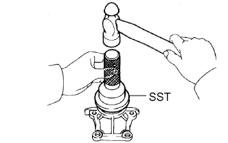
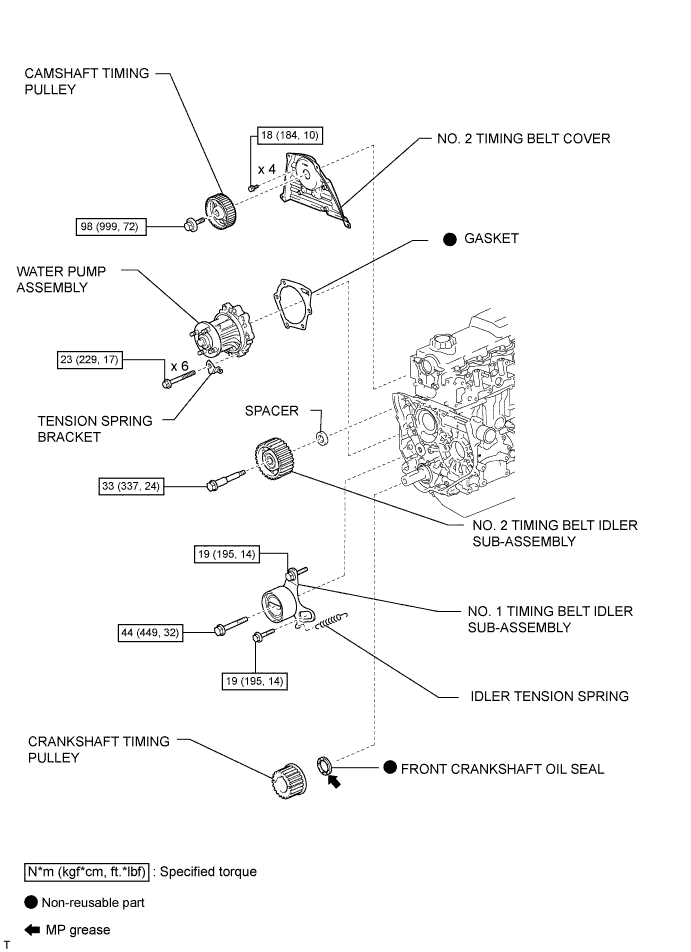
| 27. INSTALL CRANKSHAFT TIMING PULLEY |

Align the key groove of the timing pulley with the pulley set key.
Using SST and a hammer, tap in the timing pulley with the flange side facing inward.
| *a | Inside |
| 28. SET NO. 1 CYLINDER TO TDC/COMPRESSION |

Using the crankshaft pulley bolt, align the groove of the crankshaft pulley with the timing pointer by turning the crankshaft clockwise.
| *1 | Timing Mark |
 | Turn |

Set the timing and drive pulleys at each position.
| 29. INSTALL TIMING BELT |

Remove any oil or water on each pulley, and keep them clean.
Install the timing belt to the crankshaft timing and timing belt idlers.

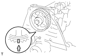
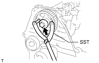
Using SST, slightly turn the injection pump drive pulley clockwise. Install the timing belt to the pulley, and align the timing marks of the drive pulley and timing belt case.
| *1 | Timing Mark |

Using SST, slightly turn the camshaft timing pulley clockwise. Install the timing belt to the timing pulley, and align the timing marks of the timing pulley and timing belt case.
| *1 | Timing Mark |
Check that the timing belt has tension between the injection pump drive and camshaft timing pulleys.
Install the timing belt to the No. 1 timing belt idler.

Loosen the No. 1 timing belt idler bolt (A), and stretch the timing belt.
Slowly turn the crankshaft pulley.
Tighten the No. 1 timing belt idler bolt.
| 30. INSTALL TIMING BELT COVER |

Install 2 new gaskets to the timing belt cover.
| *1 | Gasket |
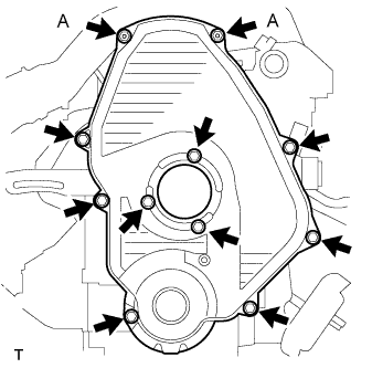
Install the timing belt cover with the 11 bolts and washers.
| 31. INSTALL CRANKSHAFT PULLEY |
Align the key groove of the pulley with the pulley set key, and slide the pulley onto the crankshaft to install it.

Using SST, install the pulley bolt.
| *a | Turn |
| *b | Hold |
| 32. INSTALL NO. 1 COMPRESSOR MOUNTING BRACKET |

Install the No. 1 compressor mounting bracket with the 4 bolts.
| 33. INSTALL ENGINE WIRE |
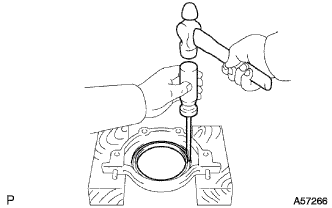
| 1. INSTALL REAR CRANKSHAFT OIL SEAL |

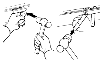
Using SST and a hammer, tap in a new oil seal until its surface is flush with the oil seal retainer edge.
Apply MP grease to lip of the oil seal.
| 2. INSTALL REAR CRANKSHAFT OIL SEAL RETAINER |
Install a new gasket and the retainer with the 4 bolts.
| 3. INSTALL FRONT CRANKSHAFT OIL SEAL |

Using SST and a hammer, tap in a new oil seal until its surface is flush with the timing belt case edge.
Apply MP grease to the lip of the oil seal.
| 4. INSTALL TIMING BELT CASE SUB-ASSEMBLY |
Place a new gasket on the cylinder block.
Install the timing belt case with the 5 bolts.
| 5. INSTALL OIL STRAINER SUB-ASSEMBLY |
Install a new gasket and the oil strainer with the 2 bolts and 2 nuts.
| 6. INSTALL OIL PAN SUB-ASSEMBLY |
Remove any old packing (FIPG) material and do not drop any oil on the contact surfaces of the oil pan and cylinder block.

Apply seal packing to the oil pan as shown in the illustration.
| Item | Seal Packing Diameter | Seal Packing Application Length |
| Dashed line | 7.0 mm (0.276 in.) | 128 mm (5.04 in.) |
| Continuous line | 5.0 mm (0.197 in.) | - |
| *1 | Seal Packing |
| *a | Timing Belt Case Contact Portion |
| *b | Rear Oil Seal Retainer Contact Portion |
Install the oil pan with the 16 bolts and 2 nuts. Uniformly tighten the bolts and nuts in several steps.
| 7. INSTALL CRANKSHAFT TIMING PULLEY |
Align the key groove of the timing pulley with the pulley set key.
Using SST and a hammer, tap in the timing pulley with the flange side facing inward.
| *a | Inside |
| 8. INSTALL NO. 1 TIMING BELT IDLER SUB-ASSEMBLY |

Install the No. 1 belt idler with the 3 bolts.

| Item | Length |
| A | 76.5 mm (3.01 in.) |
| B | 42.9 mm (1.69 in.) |
| C | 41.3 mm (1.63 in.) |
| 9. INSTALL WATER PUMP ASSEMBLY |
Install a new gasket, the water pump and tension spring bracket with the 6 bolts.
| 10. INSTALL NO. 2 TIMING BELT IDLER SUB-ASSEMBLY |
Install the spacer and No. 2 timing belt idler with the bolt.
Check that the No. 2 timing belt idler moves smoothly.
| 11. INSTALL CYLINDER HEAD GASKET |
Check the piston protrusion for each cylinder.
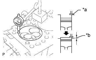
Find where the piston head protrudes most by slowly turning the crankshaft clockwise and counterclockwise.
| *a | Measuring Tip |
| *b | Protrusion |
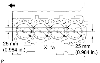
Measure the protrusion of each cylinder at 2 places as shown in the illustration, making a total of 8 measurements.
| *a | Measuring Point |
| Front |
For the piston protrusion value of each cylinder, use the average of the 2 measurements of that cylinder.
After installing the piston and connecting rod assembly, if the protrusion is not as specified, remove the piston and connecting rod assembly and reinstall them.
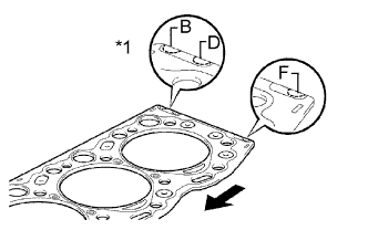
Select a new cylinder head gasket.
| *1 | Cutout Mark |
| Front |
| Item | Specified Condition |
| Mark B | 1.40 to 1.50 mm (0.0551 to 0.0591 in.) |
| Mark D | 1.50 to 1.60 mm (0.0591 to 0.0630 in.) |
| Mark F | 1.60 to 1.70 mm (0.0630 to 0.0669 in.) |
Select the largest piston protrusion value from the measurements made, then select a new appropriate gasket according to the table below.
| Piston Protrusion | Gasket Size |
| 0.68 to 0.78 mm (0.0268 to 0.0307 in.) | Use B |
| 0.78 to 0.88 mm (0.0307 to 0.0346 in.) | Use D |
| 0.88 to 0.98 mm (0.0346 to 0.0385 in.) | Use F |

Install the selected cylinder head gasket to the cylinder block.
| 12. INSTALL CYLINDER HEAD SUB-ASSEMBLY |

Using the crankshaft pulley bolt, turn the crankshaft 90° counterclockwise, and align the timing mark of the crankshaft timing pulley with the protrusion of the timing belt case.
| Turn |
Place the cylinder head on the cylinder block.
Install the plate washers to the cylinder head bolts.
Apply a light coat of engine oil to the threads and under the heads of the cylinder head bolts.
Step 1:

Install and uniformly tighten the 18 cylinder head bolts, in several steps, in the sequence shown in the illustrations.
| Item | Length |
| Bolt A | 107 mm (4.21 in.) |
| Bolt B | 127 mm (5.00 in.) |
If any one of the cylinder head bolts does not meet the torque specification, replace the cylinder set head bolt.
Step 2:
Mark the front side of each cylinder head bolt head with paint.
Tighten the cylinder head bolts 90° in the sequence shown in step 1.
Step 3:
Tighten the cylinder head bolts another 90° in the sequence shown in step 1.
Check that the paint marks are now at a 180° angle to the front.
| 13. INSTALL CAMSHAFT |

Check that the timing mark of the crankshaft timing pulley is in the position shown in the illustration.
| *1 | Timing Mark |
| *2 | Protrusion |
Install the camshaft.
Place the camshaft on the cylinder head with the key groove facing upward.

Install the 5 bearing caps in their proper locations.
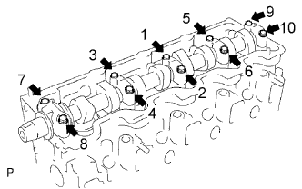
Apply a light coat of engine oil to the threads and under the heads of the bearing cap bolts.
Install and uniformly tighten the 10 bearing cap bolts in several steps in the sequence shown in the illustration.
| 14. INSTALL CAMSHAFT OIL SEAL |
Using SST and a hammer, tap in a new oil seal until its surface is flush with the oil seal retainer edge.
Apply MP grease to the lip of the oil seal.
| 15. INSTALL CAMSHAFT OIL SEAL RETAINER |
Install a new gasket and the retainer with the 4 bolts.
| 16. INSTALL CYLINDER HEAD COVER SUB-ASSEMBLY |
Remove any old packing (FIPG material).

Apply seal packing to the cylinder head as shown in the illustration.
| *1 | Seal Packing |
Install the gasket to the cylinder head cover.
Install the cylinder head cover with the 9 bolts and nut. Uniformly tighten the bolts and nut in several steps.
| 17. INSTALL NO. 2 TIMING BELT COVER |
Install the timing belt cover with the 4 bolts.
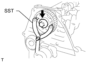
| 18. INSTALL CAMSHAFT TIMING PULLEY |
Install the woodruff key to the key groove of the camshaft.
Align the timing mark on the camshaft timing pulley with the timing mark on the No. 2 timing belt cover and temporarily install the pulley with the bolt.
Using SST, tighten the bolt.
| 19. INSTALL CRANKSHAFT POSITION SENSOR |
Apply a light coat of engine oil to the O-ring of the crankshaft position sensor.
Install the crankshaft position sensor with the bolt.
Connect the crankshaft position sensor connector.
| 1. INSPECT CAMSHAFT |
Inspect the circle runout.
Place the camshaft on V-blocks.
Using a dial indicator, measure the circle runout at the center journal.
If the circle runout is more than the maximum, replace the camshaft.
Using a micrometer, measure the cam lobe height.
| Cam Lobe | Specified Condition |
| Intake | 54.890 to 54.910 mm (2.1610 to 2.1618 in.) |
| Exhaust | 54.990 to 55.010 mm (2.1650 to 2.1657 in.) |
| cam Lobe | Specified Condition |
| Intake | 54.39 mm (2.141 in.) |
| Exhaust | 54.49 mm (2.145 in.) |
If the cam lobe height is less than the minimum, replace the camshaft.
| 2. INSPECT INTAKE MANIFOLD |

Using a precision straightedge and feeler gauge, measure the surface that contact the cylinder head for warpage.
If the warpage is more than the maximum, replace the intake manifold.
| 3. INSPECT EXHAUST MANIFOLD |

Using a precision straightedge and feeler gauge, measure the surface that contact the cylinder head for warpage.
If the warpage is more than the maximum, replace the exhaust manifold.
| 4. INSPECT CYLINDER HEAD SET BOLT |

Using a vernier caliper, measure the minimum outer diameter of the elongated thread at the measuring point.
| *a | Measuring Point |
| *b | Elongated Thread |
If the diameter is less than the minimum, replace the cylinder head set bolt.
| 1. REMOVE CRANKSHAFT POSITION SENSOR |

Disconnect the crankshaft position sensor connector.
Remove the bolt and crankshaft position sensor.
| 2. REMOVE CAMSHAFT TIMING PULLEY |

Using the crankshaft pulley bolt, turn the crankshaft 90° counterclockwise and align the timing mark of the crankshaft timing pulley with the protrusion of the timing belt case.
| Turn |
| *1 | Timing Mark |
| *2 | Protrusion |
Using SST, loosen the pulley bolt.
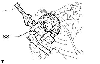
Using SST, separate the timing pulley from the camshaft.
Remove the pulley bolt and timing pulley.
Remove the timing pulley woodruff key.
| 3. REMOVE NO. 2 TIMING BELT COVER |
Remove the 4 bolts and timing belt cover.
| 4. REMOVE CYLINDER HEAD COVER SUB-ASSEMBLY |
Remove the 9 bolts, nut, cylinder head cover and gasket.
| 5. REMOVE CAMSHAFT OIL SEAL RETAINER |
Remove the 4 bolts, retainer and gasket.
| 6. REMOVE CAMSHAFT OIL SEAL |

Using a screwdriver and hammer, tap out the oil seal.
| 7. REMOVE CAMSHAFT |

Turn the camshaft with a wrench so that the key groove faces upward.
| *1 | Upward |
| *2 | Key Groove |

Uniformly loosen and remove the 10 bearing cap bolts in several steps in the sequence shown in the illustration.
Remove the 5 bearing caps and camshaft.
| 8. REMOVE CYLINDER HEAD SUB-ASSEMBLY |

Uniformly loosen and remove the 18 cylinder head bolts in several steps in the sequence shown.
Lift the cylinder head from the dowels on the cylinder block to remove it, and place the cylinder head on wooden blocks on a workbench.
| 9. REMOVE CYLINDER HEAD GASKET |
| 10. REMOVE NO. 2 TIMING BELT IDLER SUB-ASSEMBLY |
Remove the bolt, No. 2 timing belt idler and spacer.
| 11. REMOVE WATER PUMP ASSEMBLY |

Remove the 6 bolts and tension spring bracket.
Remove the water pump and gasket.
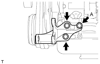
| 12. REMOVE NO. 1 TIMING BELT IDLER SUB-ASSEMBLY |
Remove the 2 bolts (A and B).

Loosen the bolt (C), and remove the No. 1 timing belt idler.
| 13. REMOVE CRANKSHAFT TIMING PULLEY |
Using a screwdriver, remove the crankshaft timing pulley.
| 14. REMOVE OIL PAN SUB-ASSEMBLY |
Remove the 16 bolts and 2 nuts.
Insert the blade of an oil pan seal cutter between the oil pan and cylinder block, cut off the applied sealer and remove the oil pan.
| 15. REMOVE OIL STRAINER SUB-ASSEMBLY |
Remove the 2 bolts, 2 nuts, oil strainer and gasket.
| 16. REMOVE TIMING BELT CASE SUB-ASSEMBLY |

Remove the 5 bolts, timing belt case and gasket.
| 17. REMOVE FRONT CRANKSHAFT OIL SEAL |

Using a screwdriver, pry out the oil seal.
| 18. REMOVE REAR CRANKSHAFT OIL SEAL RETAINER |
Remove the 4 bolts, oil seal retainer and gasket.
| 19. REMOVE REAR CRANKSHAFT OIL SEAL |
Using a screwdriver and hammer, tap out the oil seal.
| 1. REMOVE NO. 1 COMPRESSOR MOUNTING BRACKET |

Remove the 4 bolts and compressor mounting bracket.
| 2. REMOVE CRANKSHAFT PULLEY |

Using SST, remove the pulley bolt.
| *a | Hold |
| *b | Turn |
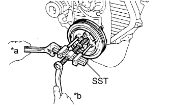
Using SST, remove the pulley.
| *a | Hold |
| *b | Turn |
| 3. REMOVE TIMING BELT COVER |

Remove the 11 bolts, washers, timing belt cover, and 2 gaskets.
| 4. SET NO. 1 CYLINDER TO TDC/COMPRESSION |
Using the crankshaft pulley bolt, align the groove of the crankshaft pulley with the timing pointer by turning the crankshaft clockwise.
| *1 | Timing Mark |
| Turn |

Check that the timing marks of the camshaft timing pulley and No. 2 timing belt cover are aligned.
| *1 | Timing Mark |
If not, turn the crankshaft 1 revolution (360°).
| 5. REMOVE TIMING BELT |
Turn the crankshaft 90° counterclockwise, and align the timing mark of the crankshaft timing pulley with the protrusion of the timing belt case.
| Turn |

Loosen the No. 1 timing belt idler bolt (A), and shift the idler to the left as far as possible.
| Pry |
 | Move |
Tighten the No. 1 timing belt idler bolt (A), and then relieve the timing belt tension.
Remove the timing belt.
| 6. REMOVE CRANKSHAFT TIMING PULLEY |
Using a screwdriver, remove the crankshaft timing pulley.
| 7. REMOVE INTAKE FLANGE |

Remove the bolt and disconnect the PCV hose and heater hose bracket.
Disconnect the manifold absolute pressure sensor connector.

Remove the 3 nuts, intake flange and gasket.
| 8. REMOVE DIESEL THROTTLE BODY |

Disconnect the throttle open switch connector.
Remove the 2 bolts and disconnect the wire harness bracket.
Disconnect the throttle control motor connector.
Remove the diesel throttle body and gasket.
| 9. REMOVE INJECTION PIPE SET |

Using a union nut wrench, loosen the 8 union nuts of the 4 injection pipes.
| *1 | Union Nut Wrench |
| *a | for Injection Nozzle Side |
| *b | for Injection Pump Side |
Remove the 2 nuts, 2 upper pipe clamps and 4 injection pipes with 2 lower pipe clamps.
| 10. REMOVE NO. 1 GLOW PLUG CONNECTOR |

Remove the nut, No. 2 glow plug resistor insulator and washer and disconnect the wire harness.
Remove the 4 screw grommets and 4 nuts.
Remove the No. 1 glow plug connector and No. 1 glow plug resistor insulator.
| 11. REMOVE NOZZLE LEAKAGE PIPE ASSEMBLY |

Disconnect the fuel hose from the leakage pipe.
Remove the 4 nuts, leakage pipe and 4 ring packing washers.
| 12. REMOVE NOZZLE HOLDER & NOZZLE SET |
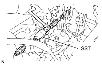
Using SST, remove the 4 injection nozzles, 4 injection nozzle seats and 4 injection nozzle seat gaskets.
| 13. REMOVE GLOW PLUG ASSEMBLY |
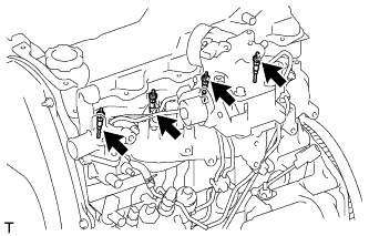
Using a 12 mm deep socket wrench, remove the 4 glow plugs.
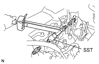
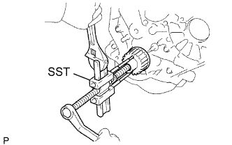
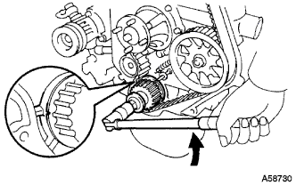
| 14. REMOVE INJECTION PUMP DRIVE PULLEY |
Using SST, remove the pulley nut.

Using SST, remove the drive pulley.
| 15. REMOVE INJECTION PUMP ASSEMBLY |
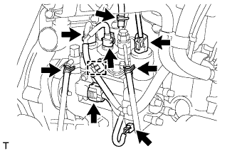
Disconnect the 5 connectors and detach the wire harness clamp.
Disconnect the 3 fuel hoses.
Remove the 3 bolts and injection pump stay.
Remove the 2 nuts and injection pump.
| 16. REMOVE CRANK POSITION SENSOR |
Disconnect the crankshaft position sensor connector.
Remove the bolt and crankshaft position sensor.
| 17. REMOVE WATER OUTLET HOUSING |
Remove the 3 bolts, outlet housing and gasket.
| 18. REMOVE INTAKE MANIFOLD |

Remove the 6 bolts, 2 nuts, intake manifold and gasket.
| 19. REMOVE WATER BY-PASS HOSE UNION |
Remove the water by-pass hose union.
| 20. REMOVE NO. 1 GENERATOR BRACKET |

Remove the 3 bolts and No. 1 generator bracket.
| 21. REMOVE PUMP BRACKET |

Remove the 3 bolts and pump bracket.
| 22. REMOVE ENGINE OIL LEVEL DIPSTICK GUIDE |
Remove the dipstick.
Remove the 2 bolts and dipstick guide.
Remove the O-ring from the dipstick guide.
| 23. REMOVE NO. 1 FRONT ENGINE MOUNTING BRACKET RH |

Remove the 4 bolts and engine mounting bracket.
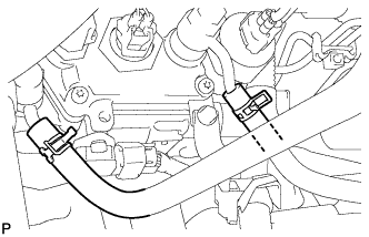
| 24. REMOVE VACUUM PUMP OIL INLET HOSE |

Remove the union bolt and gasket, and then disconnect the vacuum pump oil inlet hose from the cylinder block.
| 25. REMOVE UNION |

Remove the union from the cylinder block.
| 26. REMOVE VACUUM PUMP OIL OUTLET HOSE |

Remove the bolt, 2 gaskets and vacuum pump outlet hose.
| 27. REMOVE NO. 1 FRONT ENGINE MOUNTING BRACKET LH |
Remove the 4 bolts and engine mounting bracket.
| 28. REMOVE NO. 1 EXHAUST MANIFOLD HEAT INSULATOR |

Remove the 3 bolts and insulator.
| 29. REMOVE EXHAUST MANIFOLD |

Remove the 2 nuts, 6 bolts and manifold.
Remove the gasket.
| 30. REMOVE OIL FILTER BRACKET SUB-ASSEMBLY |

Remove the 10 bolts, 2 nuts, oil filter bracket and gasket.
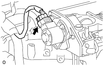
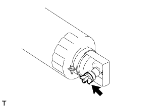
| 31. REMOVE ENGINE OIL PRESSURE SWITCH ASSEMBLY |

Using a 24 mm deep socket wrench, remove the oil pressure switch.


| 1. INSTALL FRONT ENGINE MOUNTING INSULATOR |
Install the 2 front engine mounting insulators with the 2 nuts.
| 2. INSTALL ENGINE HANGER |

Install an engine hanger to each location shown in the illustration.
| *1 | No. 1 Engine Hanger |
| *2 | No. 2 Engine Hanger |
| No. 1 Engine Hanger | 12281-54080 |
| No. 2 Engine Hanger | 12282-54070 |
| Bolt (No. 1 Engine Hanger) | 90119-10736 |
| Bolt (No. 2 Engine Hanger) | 91622-61022 |
| 3. REMOVE ENGINE FROM ENGINE STAND |
Attach an engine sling device and hang the engine with a chain block.
Lift the engine and remove it from the engine stand.
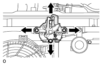
| 4. INSTALL ENGINE ASSEMBLY |
Slowly lower the engine into the engine compartment.
Install the engine with the 4 bolts and 4 nuts.

| *1 | Claw (Stopper) |
| *2 | Bracket |
| *a | Correct |
| *b | Incorrect |
Remove the 2 bolts and 2 engine hangers.
| 5. INSTALL FLYWHEEL HOUSING DUST SEAL |
| 6. INSTALL REAR END PLATE |
Install the rear end plate with the 2 bolts.
| 7. INSTALL FLYWHEEL SUB-ASSEMBLY |

Using SST, hold the crankshaft.
Clean the bolts and bolt holes.
Apply adhesive to 2 or 3 threads of each of the bolts.
Install the flywheel to the crankshaft.
Temporarily install the flywheel with the 8 bolts.

Tighten the 8 bolts uniformly in several steps in the order shown in the illustration.
| 8. INSTALL CLUTCH DISC ASSEMBLY |

Insert SST into the clutch disc. Then insert SST (together with the clutch disc) into the flywheel to install the clutch disc.
| Flywheel Side |
| 9. INSTALL CLUTCH COVER ASSEMBLY |

Align the matchmarks on the clutch cover and flywheel.
| *a | Matchmark |
Tighten the 6 bolts uniformly in the order shown in the illustration, starting with the bolt located near the knock pin on the top.
| 10. INSTALL REAR NO. 1 ENGINE MOUNTING INSULATOR |
Install the rear engine mounting insulator to the transmission with the 4 bolts.
| 11. INSTALL MANUAL TRANSMISSION ASSEMBLY |
Install the manual transmission (See page ).
| 12. INSTALL PROPELLER SHAFT ASSEMBLY |
Совместите метки на фланце карданного вала и фланце дифференциала.
Установите карданный вал в сборе и закрепите его 4 болтами, 4 шайбами и 4 гайками.
Нанесите метки на фланец карданного вала и фланец раздаточной коробки.
Закрепите карданный вал в сборе с помощью 4 шайб и 4 гаек.
| 13. INSTALL FRONT PROPELLER SHAFT ASSEMBLY |
Совместите метки на вилке и фланце дифференциала.
Установите карданный вал в сборе и закрепите его 4 болтами, 4 шайбами и 4 гайками.
Совместите метки на вилке и фланце раздаточной коробки.
Закрепите карданный вал в сборе с помощью 4 шайб и 4 гаек.
| 14. INSTALL FRONT EXHAUST PIPE ASSEMBLY |
Install a new gasket and the front exhaust pipe to the exhaust manifold with 3 new nuts.
Install the No. 1 exhaust pipe support bracket with the 2 bolts.
Install the clamp with the bolt.
| 15. INSTALL OIL FILTER SUB-ASSEMBLY |
Check and clean the oil filter installation surface.
Apply clean engine oil to the gasket of a new oil filter.
Install the oil filter and tighten it by hand until the gasket contacts the installation surface.
Using SST, tighten the oil filter. Choose from the following to further tighten the oil filter.
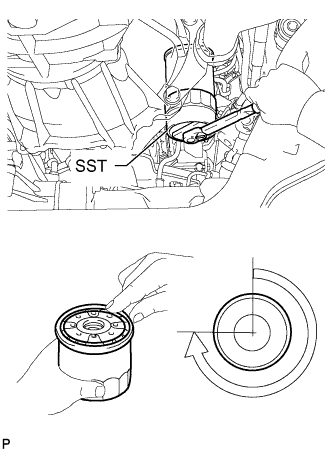
Using a torque wrench, tighten the oil filter.
Tighten the oil filter a 3/4 turn by hand or with a common wrench.
| 3/4 turn |
| 16. INSTALL STARTER ASSEMBLY |
Install the starter with the 2 bolts and nut.
Connect the starter wire with the nut.
Install the terminal cap.
Connect the starter connector.
| 17. CONNECT CLUTCH RELEASE CYLINDER ASSEMBLY |
Connect the release cylinder with the 2 bolts.
| 18. INSTALL VANE PUMP ASSEMBLY |
Temporarily install the vane pump with the 2 bolts and nut.

Install the pulley to the pump shaft.
Using SST, hold the pulley and install the nut.
| 19. CONNECT FUEL HOSE |
Connect the 2 fuel hoses.
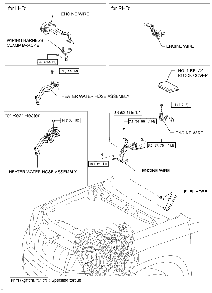
| 20. CONNECT HEATER WATER HOSE ASSEMBLY |
Connect the 2 water hoses.
Install the heater water hose clamp with the bolt.
| 21. INSTALL WIRING HARNESS CLAMP BRACKET (for LHD) |
Install the wiring harness clamp bracket with the bolt.
| 22. CONNECT ENGINE WIRE |
Connect the ECM connector.

Attach the grommet to the wire harness support.
| *1 | Grommet |
| *2 | Wire Harness Support |
Pass the wire harness into the vehicle and install the wire harness support.

Connect the 5 ECM connectors and attach the clamp.
| *A | for LHD |
| *B | for RHD |

for LHD:
Connect the 4 wire harness clamps.

Attach the 2 clamps and connect the connector.
Attach the 2 claws and install the nut.
Install the No. 1 relay block cover.
Attach the clamp and install the 3 bolts.
| 23. INSTALL GLOVE COMPARTMENT DOOR ASSEMBLY |
Install the glove compartment door (See page ).
| 24. INSTALL GENERATOR ASSEMBLY |
Temporarily install the generator with the 2 bolts.
Connect the vacuum pump oil outlet hose.
Install 2 new gaskets and the vacuum pump oil inlet hose with the union bolt.
Connect the vacuum pump hose.
Attach the vacuum pump oil inlet hose to the cord clip.
Install the generator wire with the nut.
Install the terminal cap.
Connect the generator connector.
| 25. CONNECT COOLER COMPRESSOR ASSEMBLY |

Temporarily install the cooler compressor with the 2 bolts.
Temporarily install the idle pulley bracket with the 4 bolts.
Tighten the 6 bolts in the sequence shown in the illustration.
Connect the wire harness with the bolt.
Connect the cooler compressor connector.
| 26. INSTALL INTAKE PIPE ASSEMBLY |
Install the intake pipe with the 2 bolts.
Tighten the intake pipe clamp.
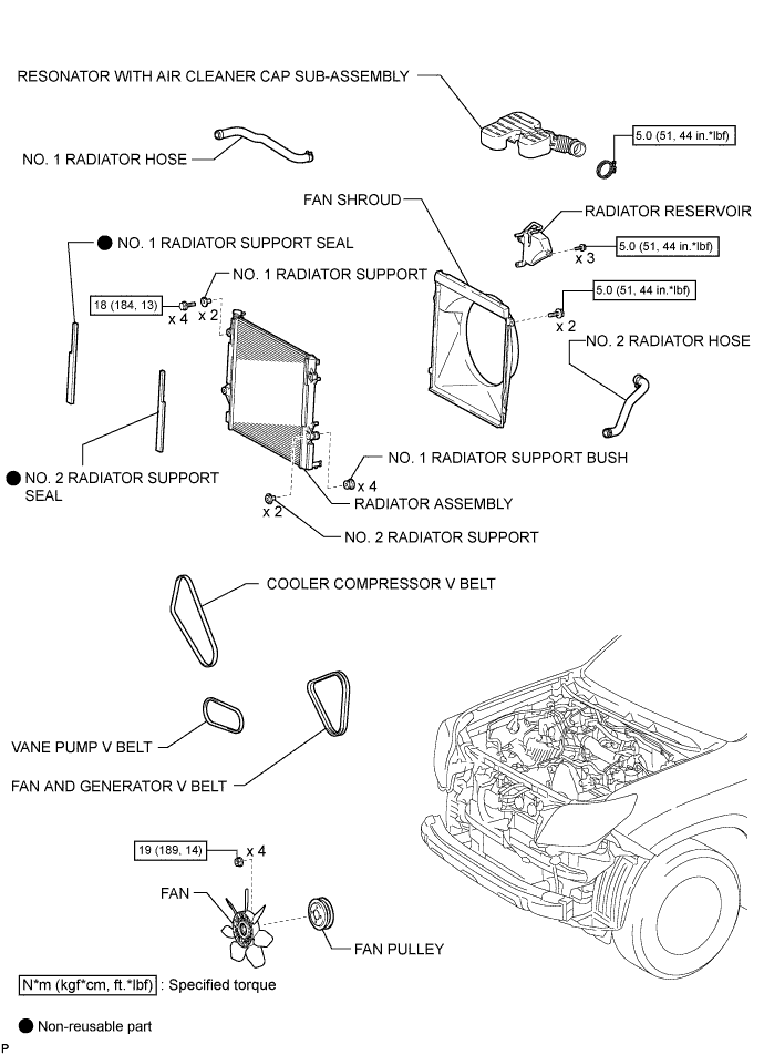
| 27. INSTALL RADIATOR ASSEMBLY |
Insert the tabs of the radiator support into the radiator service holes.
Install the radiator with the 4 bolts.
| 28. INSTALL FAN SHROUD |
Install the fan pulley to the water pump.
Install the shroud together with the coupling fan between the radiator and engine.
Temporarily install the fluid coupling fan to the fan pulley with the 4 nuts. Tighten the nuts as much as possible by hand.

Attach the claws of the shroud as shown in the illustration.
Install the shroud with the 2 bolts.
Install the fan and generator V belt and vane pump V belt (See page ).
Tighten the 4 nuts of the fluid coupling fan.
| 29. INSTALL NO. 2 RADIATOR HOSE |

Install the radiator hose.
| *a | Upper |
| *b | Front Side of Vehicle |
| *c | LH Side |
| *1 | Protrusion |
| *2 | Paint Mark |
| 30. INSTALL NO. 1 RADIATOR HOSE |
Install the hose clamp with the 2 nuts.
Install the radiator hose.
| *a | Upper |
| *b | RH Side |
| 31. INSTALL RADIATOR SIDE DEFLECTOR RH |
Attach the 3 claws.
Install the deflector with the clip.
| 32. INSTALL RADIATOR SIDE DEFLECTOR LH |
Attach the 3 claws.
Install the deflector with the clip.
| 33. INSTALL UPPER FRONT BUMPER RETAINER |
Install the upper retainer with the 3 bolts.
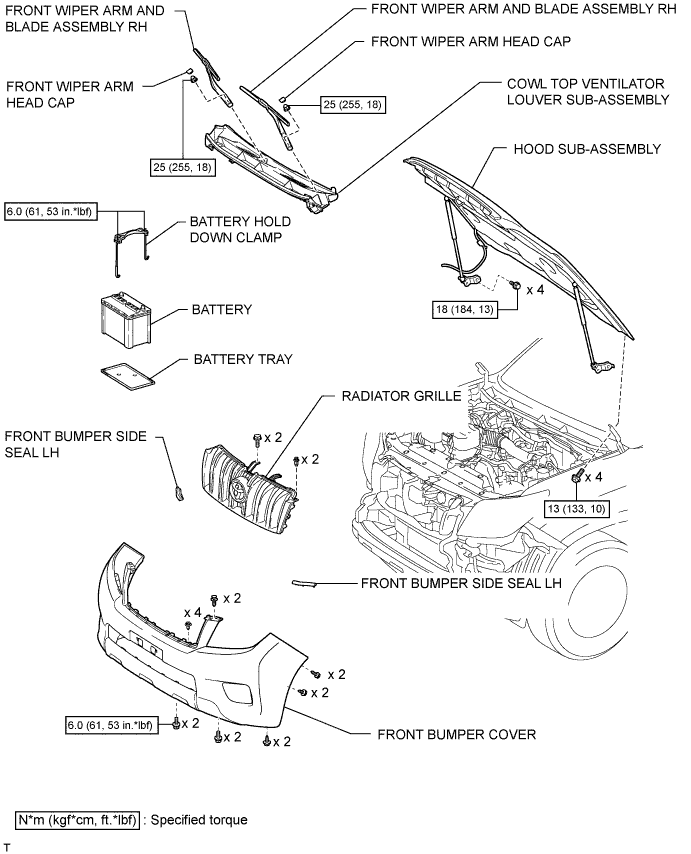
| 34. INSTALL FRONT BUMPER COVER |
Для моделей с сенсорной системой помощи при парковке TOYOTA и противотуманными фарами:
Подсоедините 3 разъема.
Для моделей с сенсорной системой помощи при парковке TOYOTA без противотуманных фар:
Подсоедините 2 разъема.
Для моделей без сенсорной системы помощи при парковке TOYOTA и с противотуманными фарами:
Подсоедините разъем.
Для моделей с системой очистителей фар:
Подсоедините шланг очистителя фар.
Закрепите 12 захватов, чтобы установить накладку переднего бампера.
Вверните 2 болта A, 2 болта B, 6 винтов и 6 фиксаторов.

| *1 | Болт A | *2 | Болт B |
| 35. INSTALL AIR CLEANER CASE ASSEMBLY |
Install the air cleaner case with the 3 bolts.
| 36. INSTALL AIR CLEANER FILTER ELEMENT SUB-ASSEMBLY |
| 37. INSTALL RESONATOR WITH AIR CLEANER CAP SUB-ASSEMBLY |
Вставьте петли крышки воздушного фильтра и шланг в корпус воздушного фильтра, а затем закрепите 4 откидных защелки.
Установите крышку воздушного фильтра и закрепите ее зажимом.
Закрепите зажим жгута проводов.
Подсоедините 2 зажима и разъем.
| 38. INSTALL NO. 1 FRONT FENDER APRON TO FRAME SEAL LH |
Install the No. 1 front fender apron to frame seal with the 5 clips.
| 39. INSTALL FRONT FENDER APRON SEAL LH |
Install the front fender apron seal with the 5 clips.
| 40. INSTALL NO. 1 FRONT FENDER APRON TO FRAME SEAL RH |
Install the No. 1 front fender apron to frame seal with the 5 clips.
| 41. INSTALL FRONT FENDER APRON SEAL RH |
Install the front fender apron seal with the 4 clips.
| 42. INSTALL REAR ENGINE UNDER COVER ASSEMBLY |
Install the rear engine under cover with the 4 bolts.
| 43. INSTALL TRANSMISSION UNDER COVER |
Install the transmission under cover with the 2 bolts.
| 44. INSTALL NO. 1 ENGINE UNDER COVER SUB-ASSEMBLY |

Hook the engine under cover to the vehicle body as shown in the illustration.
Install the 4 bolts.
| 45. INSTALL FRONT BUMPER COVER LOWER |
Install the front bumper cover lower with the 5 bolts and clip.
| 46. INSTALL UPPER RADIATOR SUPPORT SEAL |
Установите верхнее уплотнение кронштейна радиатора и закрепите его 13 фиксаторами.
| 47. INSTALL COWL TOP VENTILATOR LOUVER SUB-ASSEMBLY |
Install the cowl top ventilator louver (See page ).
| 48. INSTALL HOOD SUB-ASSEMBLY |
Install the hood with the 8 bolts.
| Bolt A |
| Bolt B |
Connect the washer nozzle hose.
| 49. ADJUST HOOD SUB-ASSEMBLY |
Отрегулируйте положение капота.
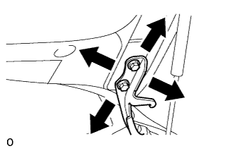
Ослабьте 4 болта петель капота.
Для регулировки зазора между капотом и передним крылом подвиньте капот.
Затяните 4 болта петель капота.
Отрегулируйте высоту передней части капота с помощью резиновых амортизаторов.
Отрегулируйте 2 резиновых амортизатора таким образом, чтобы капот и крыло оказались на одном уровне.
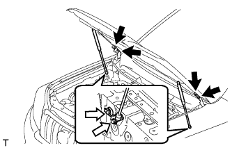
Отрегулируйте замок капота.
Ослабьте 3 болта.
Отрегулируйте замок капота и затяните 3 болта.
Убедитесь, что защелка плавно входит в зацепление с замком капота.
| 50. INSTALL BATTERY TRAY |
| 51. INSTALL BATTERY |
| 52. INSTALL BATTERY HOLD DOWN CLAMP |

Install the battery hold down clamp with the 2 nuts.
Connect the engine wire with the nut labeled A.
| 53. CONNECT CABLE TO NEGATIVE BATTERY TERMINAL |
| 54. ADD ENGINE OIL |
Add fresh engine oil.
| Oil Grade | Oil Viscosity (SAE) |
| API CF-4 or CF | 10W-30 |
| Item | Specified Condition |
| Drain and refill without oil filter change | 6.0 liters (6.3 US qts, 5.3 Imp. qts) |
| Drain and refill with oil filter change | 6.9 liters (7.3 US qts, 6.1 Imp. qts) |
| Dry fill | 7.6 liters (8.0 US qts, 6.7 Imp. qts) |
Install the oil filler cap.
| 55. ADD ENGINE COOLANT |
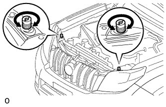
Затяните пробку сливного крана радиатора вручную.
Затяните пробку сливного крана блока цилиндров.
Медленно заполните систему охлаждающей жидкостью двигателя.
Медленно залейте охлаждающую жидкость в расширительный бачок радиатора до отметки "FULL".
Установите пробку расширительного бачка.
Несколько раз сожмите рукой патрубки радиатора № 1 и № 2, а затем проверьте уровень охлаждающей жидкости. Если уровень охлаждающей жидкости недостаточен, добавьте жидкость.
Установите на место пробку радиатора.
Запустите двигатель и прогрейте его до открывания термостата.
Поддерживайте частоту вращения коленчатого вала двигателя 2000–2500 об/мин.
Несколько раз сожмите патрубки радиатора № 1 и № 2 рукой, чтобы удалить воздух.
Остановите двигатель и подождите, пока охлаждающая жидкость остынет до температуры окружающего воздуха.
Убедитесь, что уровень охлаждающей жидкости находится между отметками "LOW" и "FULL".
Если уровень охлаждающей жидкости ниже линии "Low", повторите все вышеперечисленные действия.
Если уровень охлаждающей жидкости выше уровня "FULL", слейте охлаждающую жидкость до уровня между отметками "FULL" и "LOW".
| 56. TIGHTEN FUEL TANK CAP ASSEMBLY |
| 57. BLEED AIR FROM FUEL SYSTEM |

Using the hand pump mounted on the fuel filter cap, bleed the air from the fuel system. Continue pumping until the pump resistance increases.
| 58. INSPECT FOR FUEL LEAK |
Check that there are no fuel leaks anywhere in the fuel system after performing maintenance.
| 59. INSPECT FOR ENGINE OIL LEAK |
Start the engine. Make sure that there are no oil leaks from the areas that were worked on.
| 60. INSPECT FOR COOLANT LEAK |
Fill the radiator with coolant and attach a radiator cap tester to the radiator.
Warm up the engine.
Using a radiator cap tester, increase the pressure inside the radiator to 123 kPa (1.3 kgf/cm2, 18 psi), and check that the pressure does not drop.
If the pressure drops, check the hoses, radiator or water pump for leaks. If no external leaks are found, check the heater core, cylinder block, and cylinder head.
| 61. ADD MANUAL TRANSMISSION OIL |
| 62. INSPECT FOR GAS LEAK |
| 63. INSPECT ENGINE IDLE SPEED |
Warm up the engine.
When using the intelligent tester:
Connect the intelligent tester to the DLC3.

When not using an intelligent tester:
Using SST, connect the tachometer test probe to terminal 9 (TAC) of the DLC3.
Check the idle speed.
| *a | Front View of DLC3 |
| 64. INSPECT MAXIMUM ENGINE SPEED |
Start the engine.
Fully depress the accelerator pedal.
Check the maximum speed.
| 1. DISCONNECT CABLE FROM NEGATIVE BATTERY TERMINAL |
| 2. REMOVE BATTERY HOLD DOWN CLAMP |

Remove the nut and disconnect the engine wire.
Remove the 2 nuts and battery hold down clamp.
| 3. REMOVE BATTERY |
| 4. REMOVE BATTERY TRAY |
| 5. REMOVE HOOD SUB-ASSEMBLY |
Disconnect the washer nozzle hose.

Remove the 8 bolts and hood.
| 6. REMOVE COWL TOP VENTILATOR LOUVER SUB-ASSEMBLY |
Remove the cowl top ventilator louver (See page ).
| 7. REMOVE UPPER RADIATOR SUPPORT SEAL |
Освободите 13 фиксаторов и снимите верхнее уплотнение кронштейна радиатора.
| 8. REMOVE FRONT BUMPER COVER LOWER |
Remove the clip, 5 bolts and front bumper cover lower.
| 9. REMOVE NO. 1 ENGINE UNDER COVER SUB-ASSEMBLY |
Remove the 4 bolts.
Unhook the engine under cover from the vehicle body as shown in the illustration.
| 10. REMOVE TRANSMISSION UNDER COVER |
Remove the 2 bolts and transmission under cover.
| 11. REMOVE REAR ENGINE UNDER COVER ASSEMBLY |
Remove the 4 bolts and rear engine under cover.
| 12. DRAIN ENGINE COOLANT |
Ослабьте пробку сливного крана радиатора.

| *1 | Пробка радиатора | *2 | Бачок радиатора |
| *3 | Пробка сливного крана радиатора | *4 | Пробка сливного крана блока цилиндров |
Слейте охлаждающую жидкость, сняв крышку радиатора.
Ослабьте пробку сливного крана блока цилиндров.
Ослабьте пробку сливного крана блока цилиндров и слейте охлаждающую жидкость из двигателя.
| 13. DRAIN ENGINE OIL |
Remove the oil filler cap.
Remove the oil drain plug and gasket, and then drain the oil into a container.
Clean the drain plug and install it with a new gasket.
| 14. REMOVE FRONT FENDER APRON SEAL RH |
Remove the 4 clips and fender apron seal.
| 15. REMOVE NO. 1 FRONT FENDER APRON TO FRAME SEAL RH |
Remove the 5 clips and frame seal.
| 16. REMOVE FRONT FENDER APRON SEAL LH |
Remove the 5 clips and fender apron seal.
| 17. REMOVE NO. 1 FRONT FENDER APRON TO FRAME SEAL LH |
Remove the 5 clips and frame seal.
| 18. REMOVE RESONATOR WITH AIR CLEANER CAP SUB-ASSEMBLY |

Disconnect the sensor connector.
Detach the wire harness clamp.
Loosen the hose clamp and remove the resonator with air cleaner cap.

Detach the 4 hook clamps, and then remove the air cleaner cap and resonator with air cleaner cap.
| 19. REMOVE AIR CLEANER FILTER ELEMENT SUB-ASSEMBLY |
| 20. REMOVE AIR CLEANER CASE ASSEMBLY |

Remove the 3 bolts and air cleaner case.
| 21. REMOVE FRONT BUMPER COVER |
Наклейте защитную ленту вокруг накладки переднего бампера.
Выверните 2 болта A и 2 болта B.
Выверните 6 винтов и освободите 6 фиксаторов.
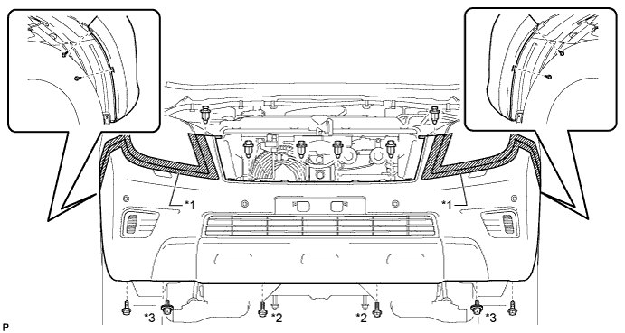
| *1 | Защитная клейкая лента | *2 | Болт A |
| *3 | Болт B | - | - |
Освободите 12 захватов.
Для моделей с сенсорной системой помощи при парковке TOYOTA и противотуманными фарами:
Отсоедините 3 разъема.
Для моделей с сенсорной системой помощи при парковке TOYOTA без противотуманных фар:
Отсоедините разъем.
Для моделей без сенсорной системы помощи при парковке TOYOTA и с противотуманными фарами:
Отсоедините 2 разъема.
Для моделей с системой очистителей фар:
Отсоедините шланг очистителя фар.
Снимите облицовку переднего бампера.
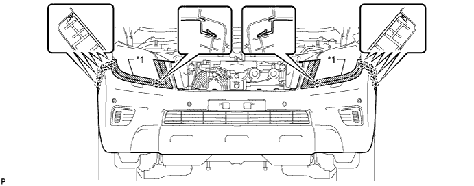
| *1 | Защитная клейкая лента | - | - |
| 22. REMOVE FRONT UPPER BUMPER RETAINER |

Remove the 3 bolts and retainer.
| 23. REMOVE RADIATOR SIDE DEFLECTOR LH |

Using a clip remover, detach the 3 claws and remove the clip. Then move the side deflector so that the radiator can be removed in the step below.
| 24. REMOVE RADIATOR SIDE DEFLECTOR RH |
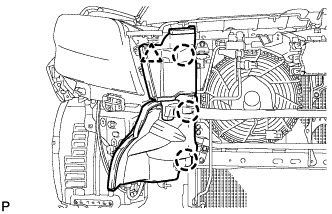
Using a clip remover, detach the 3 claws and remove the clip. Then move the side deflector so that the radiator can be removed in the step below.
| 25. REMOVE NO. 1 RADIATOR HOSE |

Detach the clamp and remove the No. 1 radiator hose.

Remove the 2 nuts and hose clamp.
| 26. REMOVE NO. 2 RADIATOR HOSE |
| 27. REMOVE FAN SHROUD |

Loosen the 4 nuts holding the fluid coupling fan.
Remove the vane pump V belt and the fan and generator V belt (See page ).

Remove the 2 bolts holding the fan shroud.
Remove the 4 nuts of the fluid coupling fan, and then remove the shroud together with the coupling fan.
Remove the fan pulley from the water pump.
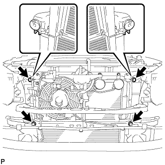
| 28. REMOVE RADIATOR ASSEMBLY |

Remove the 4 bolts and radiator.
| 29. REMOVE INTAKE PIPE ASSEMBLY |

Loosen the hose clamp and remove the 2 bolts and intake pipe.
| 30. DISCONNECT COOLER COMPRESSOR ASSEMBLY |

Remove the 4 bolts and idle pulley bracket.
Disconnect the connector.
Remove the 3 bolts and disconnect the cooler compressor.
| 31. REMOVE GENERATOR ASSEMBLY |

Remove the terminal cap.
Remove the nut and generator wire.
Disconnect the generator connector.
Disconnect the vacuum pump hose.
Remove the union bolt to disconnect the vacuum pump oil inlet hose and remove the 2 gaskets.
Detach the vacuum pump oil inlet hose from the cord clip.
Disconnect the vacuum pump oil outlet hose.

Remove the 2 bolts and generator.
| 32. REMOVE GLOVE COMPARTMENT DOOR ASSEMBLY |
Remove the glove compartment door (See page ).
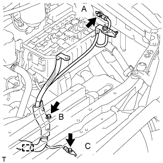
| 33. DISCONNECT ENGINE WIRE |

Remove the 3 bolts, detach the clamp and disconnect the engine wire.
Remove the No. 1 relay block cover.
Remove the nut and detach the 2 claws.
Disconnect the connector.
Detach the 2 clamps and disconnect the engine wire.
for LHD:
Detach the 4 clamps.

Detach the grommet from the wire harness support.
| *A | for LHD |
| *B | for RHD |

Detach the 4 claws to remove the wire harness support from the vehicle, and then pull out the ECM connector to remove it from the vehicle.
| *A | for LHD |
| *B | for RHD |
Detach the clamp and disconnect the 5 connectors as shown in the illustration.
| *A | for LHD |
| *B | for RHD |
| 34. REMOVE WIRING HARNESS CLAMP BRACKET (for LHD) |
Remove the bolt and wiring harness clamp bracket.
| 35. DISCONNECT HEATER WATER HOSE ASSEMBLY |

Remove the bolt and disconnect the heater water hoses.
| *A | for Rear Heater |
| 36. LOOSEN FUEL TANK CAP ASSEMBLY |
| 37. DRAIN FUEL |
Loosen the fuel filter drain plug and drain the fuel from the fuel filter.
| 38. DISCONNECT FUEL HOSE |
Disconnect the 2 fuel hoses.
| 39. DISCONNECT VANE PUMP ASSEMBLY |

Using SST, hold the pulley and loosen the nut.
Remove the nut and vane pump pulley from the vane pump shaft.
Remove the 2 bolts and nut and disconnect the vane pump.
| 40. REMOVE CLUTCH RELEASE CYLINDER ASSEMBLY |

Remove the 2 bolts and disconnect the release cylinder.
| 41. REMOVE STARTER ASSEMBLY |

Disconnect the starter connector.
Remove the terminal cap.
Remove the nut and disconnect the starter wire.

Remove the nut, 2 bolts and starter.
| 42. REMOVE OIL FILTER SUB-ASSEMBLY |

Using SST, remove the oil filter.
| 43. REMOVE FRONT EXHAUST PIPE ASSEMBLY |
Remove the bolt from the clamp.

Remove the 2 bolts and No. 1 exhaust pipe support bracket.

Remove the 3 nuts and front exhaust pipe.
Remove the gasket.
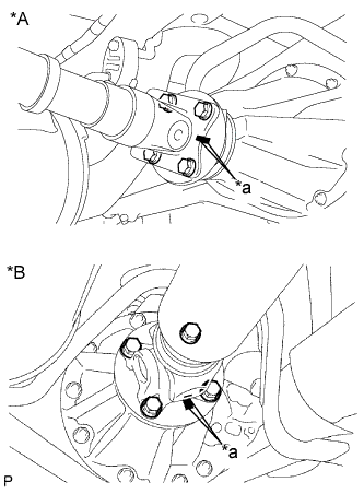
| 44. REMOVE FRONT PROPELLER SHAFT ASSEMBLY |

Нанесите метки на фланец карданного вала и дифференциал.
| *a | Метка |
Снимите 4 гайки, 4 болта, 4 шайбы и передний карданный вал в сборе.

Нанесите метки на фланец карданного вала и фланец раздаточной коробки.
| *a | Метка |
Отверните 4 гайки и снимите 4 шайбы и передний карданный вал в сборе.
| 45. REMOVE PROPELLER SHAFT ASSEMBLY |

Нанесите метки на фланец карданного вала и фланец раздаточной коробки.
| *A | Для 3-дверных моделей: |
| *B | Для 5-дверных моделей: |
| *a | Метка |
Отверните 4 гайки и снимите 4 шайбы.
Нанесите метки на фланец карданного вала и фланец дифференциала.
| *A | Для 3-дверных моделей: |
| *B | Для 5-дверных моделей: |
| *a | Метка |
Отверните 4 гайки и снимите 4 болта и 4 шайбы.
Снимите карданный вал.
| 46. REMOVE MANUAL TRANSMISSION ASSEMBLY |
Remove the manual transmission (See page ).
| 47. REMOVE REAR NO. 1 ENGINE MOUNTING INSULATOR |

Remove the 4 bolts and rear engine mounting insulator from the transmission.
| 48. REMOVE CLUTCH COVER ASSEMBLY |
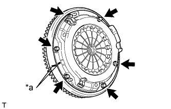
Place matchmarks on the clutch cover and flywheel.
| *a | Matchmark |
Loosen each set bolt one turn at a time until spring tension is released.
Remove the 6 set bolts and pull off the clutch cover.
| 49. REMOVE CLUTCH DISC ASSEMBLY |
| 50. REMOVE FLYWHEEL SUB-ASSEMBLY |
Using SST, hold the crankshaft.
Remove the 8 bolts and flywheel.
| 51. REMOVE REAR END PLATE |
Remove the 2 bolts and rear end plate.
| 52. REMOVE FLYWHEEL HOUSING DUST SEAL |
| 53. INSTALL ENGINE HANGER |
Install an engine hanger to each location shown in the illustration.
| *1 | No. 1 Engine Hanger |
| *2 | No. 2 Engine Hanger |
| No. 1 Engine Hanger | 12281-54080 |
| No. 2 Engine Hanger | 12282-54070 |
| Bolt (No. 1 Engine Hanger) | 90119-10736 |
| Bolt (No. 2 Engine Hanger) | 91622-61022 |
| 54. REMOVE ENGINE ASSEMBLY |
Attach an engine sling device and hang the engine with a chain block.

Remove the 4 nuts and 4 bolts from the front engine mounting insulator LH and RH.
| *1 | for RH Side |
| *2 | for LH Side |
Remove the engine by operating the engine sling device and chain block.
| 55. INSTALL ENGINE TO ENGINE STAND |
Install the engine to an engine stand with bolts.
Remove engine hanger.
| 56. REMOVE ENGINE WIRE |
Remove the engine wire from the engine.
| 57. REMOVE FRONT ENGINE MOUNTING INSULATOR |

Remove the 2 nuts and 2 front engine mounting insulators.