Dtc B2764 Short To Gnd In Intrusion Sensor Signal Circuit
DESCRIPTION
WIRING DIAGRAM
INSPECTION PROCEDURE
CHECK INTRUSION SENSOR (IOUT)
CHECK INTRUSION SENSOR (IOUT)
CHECK HARNESS AND CONNECTOR (MAP LIGHT - CERTIFICATION ECU [SMART KEY ECU ASSEMBLY])
DTC B2764 Short to GND in Intrusion Sensor Signal Circuit
DESCRIPTION
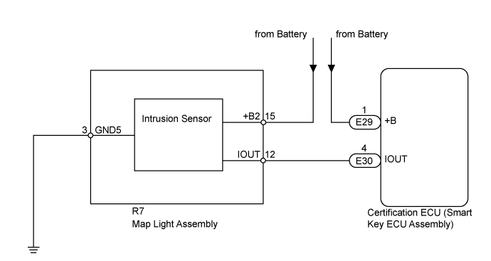
The intrusion sensor (theft warning ultrasonic sensor) conducts self-diagnosis immediately after power is supplied to the sensor (when the theft deterrent system is set).
If a malfunction is detected in the ISIF line, the certification ECU (smart key ECU assembly) stores this DTC.
| DTC Code | DTC Detection Condition | Trouble Area |
| B2764 | After normal/trouble signal is output from intrusion sensor as result of self-diagnosis, following malfunctions are detected:
IOUT line circuit is shorted to ground
Reception of signals other than normal/ trouble signal
| Map light assembly
Certification ECU (smart key ECU assembly)
Harness or connector
|
WIRING DIAGRAM
INSPECTION PROCEDURE
| 1.CHECK INTRUSION SENSOR (IOUT) |
Using an oscilloscope, check the waveform.
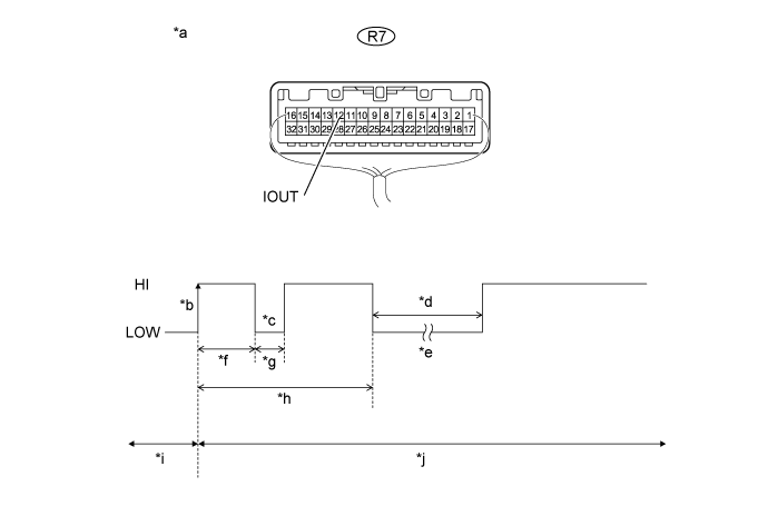
Text in Illustration| *a | Component with harness connected
(Map Light Assembly) | *b | IOUT Initial Signal |
| *c | IOUT Initial Response | *d | Approximately 1.0 seconds |
| *e | Initial Diagnosis | *f | Approximately 1.0 to 1.6 seconds |
| *g | Approximately 0.05 seconds | *h | Approximately 5.5 seconds |
| *i | Disarmed State | *j | Arming Preparation State |
Measurement Condition| Tester Connection | Content |
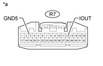
| Tester Connection | R7-12 (IOUT) - Body ground |
| Tool Setting | 2 V/DIV., 100 ms./DIV. |
| Condition | Theft deterrent system is set (system changes from disarmed state to arming preparation state) |
If the intrusion sensor is normal, an initial response is output in response to the HI input from the certification ECU (smart key ECU assembly).
If the waveform output remains LO, there may be a problem with the certification ECU (smart key ECU assembly), as there is no input from the certification ECU (smart key ECU assembly).
- OK:
- The waveform displays properly (HI is 6.5 V or higher and LO is below 1 V).
| OK | |
| |
| USE SIMULATION METHOD TO CHECK ()
|
|
| 2.CHECK INTRUSION SENSOR (IOUT) |
Disconnect the map light assembly connector.
Measure the voltage according to the value(s) in the table below.
- Standard Voltage:
| Tester Connection | Condition |
| R7-12 (IOUT) - R7-3 (GND5) | Immediately after theft deterrent system set |
Result| Result | Proceed to |
| IOUT voltage is below 1 V when theft deterrent system is set | A |
| IOUT voltage is 6.5 V or higher when theft deterrent system is set | B |
- With connector R7 of the map light assembly disconnected, measure the voltage at IOUT when the theft deterrent system is set.
| | REPLACE MAP LIGHT ASSEMBLY ()
|
|
|
| 3.CHECK HARNESS AND CONNECTOR (MAP LIGHT - CERTIFICATION ECU [SMART KEY ECU ASSEMBLY]) |
Disconnect the R7 map light assembly connector.
Disconnect the E30 certification ECU (smart key ECU assembly) connector.
Measure the resistance according to the value(s) in the table below.
- Standard Resistance:
| Tester Connection | Condition | Specified Condition |
| R7-12 (IOUT) - E30-4 (IOUT) | Always | Below 1 Ω |
| R7-12 (IOUT) or E30-4 (IOUT) - Body ground | Always | 10 kΩ or higher |
| | REPAIR OR REPLACE HARNESS OR CONNECTOR |
|
|
| OK | |
| |
| REPLACE CERTIFICATION ECU (SMART KEY ECU ASSEMBLY) |
|