Dtc B279A Theft Deterrent System Communication Line High Fixation
DESCRIPTION
WIRING DIAGRAM
INSPECTION PROCEDURE
CLEAR DTC
CHECK FOR DTC
CHECK HARNESS AND CONNECTOR (ID CODE BOX (IMMOBILISER CODE ECU) - ECM)
CHECK ID CODE BOX (IMMOBILISER CODE ECU) (OUTPUT)
CHECK ID CODE BOX (IMMOBILISER CODE ECU) (POWER SOURCE AND BODY GROUND)
DTC B279A Theft Deterrent System Communication Line High Fixation
DESCRIPTION
If the communication line (EFIO-IMI) to the ID code box (immobiliser code ECU) is stuck on HI output, the ECM outputs this DTC.
| DTC Code | DTC Detection Condition | Trouble Area |
| B279A | When the communication line (EFIO-IMI) between the ECM and the ID code box (immobiliser code ECU) is stuck on HI output. | Harness or connector
ID code box (immobiliser code ECU)
ECM
|
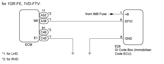
WIRING DIAGRAM


INSPECTION PROCEDURE
Check for DTCs ().
- If DTCs other than DTC B279A are output, troubleshoot those DTCs first.
Result| Result | Proceed to |
| DTC B279A is output | A |
| DTC B279A and other DTCs are output | B |
| | Go to DIAGNOSTIC TROUBLE CODE CHART ()
|
|
|
| 3.CHECK HARNESS AND CONNECTOR (ID CODE BOX (IMMOBILISER CODE ECU) - ECM) |
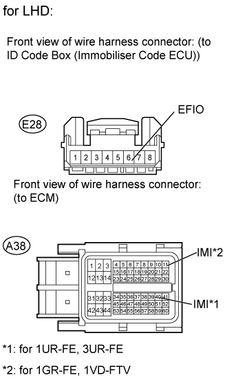
Disconnect the E28 ID code box connector.
Disconnect the A38*1 or A52*2 ECU connector.
Measure the resistance and voltage according to the value(s) in the table below.
for 1UR-FE
- Standard Resistance:
| Tester Connection | Condition | Specified Condition |
| E28-6 (EFIO) - A38*1-40 (IMI) | Always | Below 1 Ω |
| E28-6 (EFIO) or A38*1-40 (IMI) - Body ground | Always | 10 kΩ or higher |
| E28-6 (EFIO) - A52*2-40 (IMI) | Always | Below 1 Ω |
| E28-6 (EFIO) or A52*2-40 (IMI) - Body ground | Always | 10 kΩ or higher |
- Standard Voltage:
| Tester Connection | Condition | Specified Condition |
| E28-6 (EFIO) - Body ground | Always | Below 1 V |
| A38*1-40 (IMI) - Body ground |
| A52*2-40 (IMI) - Body ground |
for 1GR-FE, 1VD-FTV
- Standard Resistance:
| Tester Connection | Condition | Specified Condition |
| E28-6 (EFIO) - A38*1-11 (IMI) | Always | Below 1 Ω |
| E28-6 (EFIO) or A38*1-11 (IMI) - Body ground | Always | 10 kΩ or higher |
| E28-6 (EFIO) - A52*2-11 (IMI) | Always | Below 1 Ω |
| E28-6 (EFIO) or A52*2-11 (IMI) - Body ground | Always | 10 kΩ or higher |
- Standard Voltage:
| Tester Connection | Condition | Specified Condition |
| E28-6 (EFIO) - Body ground | Always | Below 1 V |
| A38*1-11 (IMI) - Body ground |
| A52*2-11 (IMI) - Body ground |
for 3UR-FE
- Standard Resistance:
| Tester Connection | Condition | Specified Condition |
| E28-6 (EFIO) - A38-40 (IMI) | Always | Below 1 Ω |
| E28-6 (EFIO) or A38-40 (IMI) - Body ground | Always | 10 kΩ or higher |
- Standard Voltage:
| Tester Connection | Condition | Specified Condition |
| E28-6 (EFIO) - Body ground | Always | Below 1 V |
| A38-40 (IMI) - Body ground |
| | REPAIR OR REPLACE HARNESS OR CONNECTOR |
|
|
| 4.CHECK ID CODE BOX (IMMOBILISER CODE ECU) (OUTPUT) |
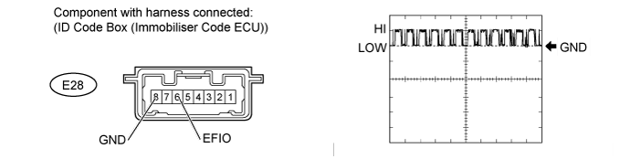
Using an oscilloscope, check the waveform.
Measurement Condition| Item | Content |
| Tester Connection | E28-6 (EFIO) - E28-8 (GND) |
| Tool Setting | 10 V/DIV., 100 msec./DIV. |
| Condition | Engine switch on (IG) |
- OK:
- Waveform is output normally (see illustration).
Result| Result | Proceed to |
| NG | A |
| OK (for 1GR-FE) | B |
| OK (for 1UR-FE) | C |
| OK (for 1VD-FTV) | D |
| OK (for 3UR-FE) | E |
| 5.CHECK ID CODE BOX (IMMOBILISER CODE ECU) (POWER SOURCE AND BODY GROUND) |
Turn the engine switch on (IG).
Measure the voltage according to the value(s) in the table below.
- Standard Voltage:
| Tester Connector | Condition | Specified Condition |
| E28-1 (+B) - E28-8 (GND) | Always | 11 to 14 V |
| | REPAIR OR REPLACE HARNESS OR CONNECTOR |
|
|
| OK | |
| |
| REPLACE ID CODE BOX (IMMOBILISER CODE ECU) |
|