Land Cruiser URJ200 URJ202 GRJ200 VDJ200 - NETWORKING
CAN COMMUNICATION SYSTEM (for LHD) - TERMINALS OF ECU
- HINT:
- Operating the ignition switch, any switches or any doors triggers related ECU and sensor communication with the CAN, which causes resistance variation.
| DISCONNECT CABLE FROM NEGATIVE BATTERY TERMINAL |
Disconnect the cable from the negative (-) battery terminal before measuring the resistances of the CAN main wire and CAN branch wire.
- CAUTION:
- For vehicle with an SRS system:
- Wait at least 90 seconds after disconnecting the cable from the negative (-) battery terminal to disable the SRS system.
- NOTICE:
| JUNCTION CONNECTOR |
NO. 1 JUNCTION CONNECTOR

| *a | for No. 2 Junction Connector | *b | for ECM |
| *c | for Headlight Swivel ECU Assembly (w/ Dynamic Headlight Auto Leveling) | *d | for Center Airbag Sensor Assembly (w/ Airbag System) |
| *e | for 4WD Control ECU (w/o Network Gateway ECU) | - | - |
| No. 1 Junction Connector | Wiring Color | Connect to |
| E72-1 (CANH) | Y*4, SB*5 | No. 2 junction connector |
| E72-12 (CANL) | B | |
| E72-2 (CANH) | P | ECM |
| E72-13 (CANL) | B | |
| E72-3 (CANH) | LG | Headlight swivel ECU assembly*1 |
| E72-14 (CANL) | B | |
| E72-4 (CANH) | GR | Center airbag sensor assembly*2 |
| E72-15 (CANL) | B | |
| E72-5 (CANH) | P | 4WD control ECU*3 |
| E72-16 (CANL) | L |
NO. 2 JUNCTION CONNECTOR

| *a | for No. 1 Junction Connector | *b | for Multi-media Module Receiver Assembly (w/ Navigation System) |
| *c | for Network Gateway ECU (V Bus) (w/ Network Gateway ECU) | *d | for No. 3 Junction Connector (w/ Network Gateway ECU) for No. 6 Junction Connector (w/o Network Gateway ECU) |
| *e | for Air Conditioning Amplifier Assembly | - | - |
| No. 2 Junction Connector | Wiring Color | Connect to |
| E69-1 (CANH) | Y*4, SB*5 | No. 1 junction connector |
| E69-12 (CANL) | B | |
| E69-2 (CANH) | P | Multi-media module receiver assembly*1 |
| E69-13 (CANL) | B | |
| E69-3 (CANH) | BR*4, BE*5 | Network gateway ECU (V bus)*2 |
| E69-14 (CANL) | B | |
| E69-4 (CANH) | W*2, *4 Y*3, *4 SB*5 | No. 3 junction connector*2 No. 6 junction connector*3 |
| E69-15 (CANL) | B*2 L*3 | |
| E69-5 (CANH) | G | Air conditioning amplifier assembly |
| E69-16 (CANL) | B |
NO. 3 JUNCTION CONNECTOR

| *a | for No. 2 Junction Connector (w/ Network Gateway ECU) for No. 6 Junction Connector (w/o Network Gateway ECU) | *b | for DLC3 |
| *c | for Combination Meter Assembly (V Bus) | *d | for Main Body ECU (Cowl Side Junction Block LH) (V Bus) |
| *e | for Master Cylinder Solenoid (Skid Control ECU) (w/o Network Gateway ECU) | - | - |
| No. 3 Junction Connector | Wiring Color | Connect to |
| E75-1 (CANH) | W*1, *3 Y*2, *3 SB*4 | No. 2 junction connector*1 No. 6 junction connector*2 |
| E75-12 (CANL) | B*1 L*2 | |
| E75-2 (CANH) | G | DLC3 |
| E75-13 (CANL) | B | |
| E75-3 (CANH) | V | Combination meter assembly (V bus) |
| E75-14 (CANL) | B | |
| E75-4 (CANH) | SB | Main body ECU (cowl side junction block LH) (V bus) |
| E75-15 (CANL) | B | |
| E75-5 (CANH) | V | Master cylinder solenoid (skid control ECU)*2 |
| E75-16 (CANL) | L |
NO. 4 JUNCTION CONNECTOR (w/ Network Gateway ECU)
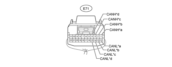
| *a | for No. 5 Junction Connector | *b | for Network Gateway ECU (Movement Control Bus) |
| *c | for 4WD Control ECU | *d | for Power Steering ECU Assembly (for 1VD-FTV with DPF) |
| No. 4 Junction Connector | Wiring Color | Connect to |
| E71-1 (CANH) | W | No. 5 junction connector |
| E71-12 (CANL) | L | |
| E71-2 (CANH) | SB | Network gateway ECU (Movement control bus) |
| E71-13 (CANL) | L | |
| E71-3 (CANH) | P | 4WD control ECU |
| E71-14 (CANL) | L | |
| E71-4 (CANH) | LG | Power steering ECU assembly* |
| E71-15 (CANL) | L |
NO. 5 JUNCTION CONNECTOR (w/ Network Gateway ECU)
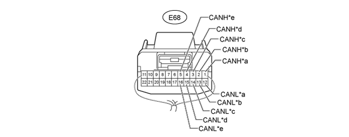
| *a | for No. 4 Junction Connector | *b | for No. 6 Junction Connector |
| *c | for Yaw Rate Sensor Assembly (w/ Vehicle Stability Control System) | *d | for Distance Control ECU Assembly (w/ Dynamic Radar Cruise Control System) |
| *e | for Seat Belt Control ECU (w/ Pre-crash Safety System) | - | - |
| No. 5 Junction Connector | Wiring Color | Connect to |
| E68-1 (CANH) | W | No. 4 junction connector |
| E68-12 (CANL) | L | |
| E68-2 (CANH) | Y*4, SB*5 | No. 6 junction connector |
| E68-13 (CANL) | L | |
| E68-3 (CANH) | BR | Yaw rate sensor assembly*1 |
| E68-14 (CANL) | L | |
| E68-4 (CANH) | SB | Distance control ECU assembly*2 |
| E68-15 (CANL) | L | |
| E68-5 (CANH) | G | Seat belt control ECU*3 |
| E68-16 (CANL) | L |
NO. 6 JUNCTION CONNECTOR

| *a | for Clearance Warning ECU Assembly (w/ TOYOTA Parking Assist-sensor System and w/o Side Monitor System) for Parking Assist ECU (w/ Side Monitor System) | *b | for No. 7 Junction Connector (w/ Network Gateway ECU) for No. 3 Junction Connector (w/o Network Gateway ECU) |
| *c | for No. 5 Junction Connector (w/ Network Gateway ECU) for No. 2 Junction Connector (w/o Network Gateway ECU) | - | - |
| No. 6 Junction Connector | Wiring Color | Connect to |
| F73-5 (CANH) | V | Clearance warning ECU assembly*1 Parking assist ECU*2 |
| F73-16 (CANL) | L | |
| F73-6 (CANH) | Y*5, SB*6 | No. 7 junction connector*3 No. 3 junction connector*4 |
| F73-17 (CANL) | L | |
| F73-7 (CANH) | Y*5, SB*6 | No. 5 junction connector*3 No. 2 junction connector*4 |
| F73-18 (CANL) | L |
NO. 7 JUNCTION CONNECTOR (w/ Network Gateway ECU)

| *a | for No. 1 CAN Junction Connector | *b | for No. 6 Junction Connector |
| *c | for Steering Control ECU (w/ Variable Gear Ratio Steering System) | *d | for Steering Angle Sensor (w/ Vehicle Stability Control System) |
| *e | for Master Cylinder Solenoid (Skid Control ECU) | - | - |
| No. 7 Junction Connector | Wiring Color | Connect to |
| E74-1 (CANH) | W | No. 1 CAN junction connector |
| E74-12 (CANL) | L | |
| E74-2 (CANH) | Y*3, SB*4 | No. 6 junction connector |
| E74-13 (CANL) | L | |
| E74-3 (CANH) | LG | Steering control ECU*1 |
| E74-14 (CANL) | L | |
| E74-4 (CANH) | GR | Steering angle sensor*2 |
| E74-15 (CANL) | L | |
| E74-5 (CANH) | V | Master cylinder solenoid (skid control ECU) |
| E74-16 (CANL) | L |
NO. 8 JUNCTION CONNECTOR

| *a | for No. 2 CAN Junction Connector | *b | for Certification ECU (Smart Key ECU Assembly) (w/ Entry and Start System) |
| *c | for Multiplex Tilt and Telescopic ECU (w/ Power Tilt and Power Telescopic Steering Column System) | *d | for Position Control ECU and Switch (w/ Seat Memory) |
| *e | for Outer Mirror Control ECU Assembly (w/ Seat Memory) | *f | for Main Body ECU (Cowl Side Junction Block LH) (MS Bus) |
| No. 8 Junction Connector | Wiring Color | Connect to |
| E76-1 (CANH) | W | No. 2 CAN junction connector |
| E76-12 (CANL) | R | |
| E76-2 (CANH) | LG | Certification ECU (smart key ECU assembly)*1 |
| E76-13 (CANL) | R | |
| E76-3 (CANH) | P | Multiplex tilt and telescopic ECU*2 |
| E76-14 (CANL) | R | |
| E76-4 (CANH) | V | Position control ECU and switch*3 |
| E76-15 (CANL) | R | |
| E76-5 (CANH) | BR | Outer mirror control ECU assembly*3 |
| E76-16 (CANL) | R | |
| E76-6 (CANH) | GR | Main body ECU (cowl side junction block LH) (MS bus) |
| E76-17 (CANL) | R |
NO. 9 JUNCTION CONNECTOR

| *a | for No. 10 Junction Connector | *b | for No. 2 CAN Junction Connector |
| *c | for Accessory Bus Buffer | *d | for Windshield Wiper ECU (w/ Rain Sensor) |
| No. 9 Junction Connector | Wiring Color | Connect to |
| E73-1 (CANH) | W | No. 10 junction connector |
| E73-12 (CANL) | R | |
| E73-2 (CANH) | Y | No. 2 CAN junction connector |
| E73-13 (CANL) | R | |
| E73-3 (CANH) | V | Accessory bus buffer |
| E73-14 (CANL) | R | |
| E73-4 (CANH) | LG | Windshield wiper ECU* |
| E73-15 (CANL) | R |
NO. 10 JUNCTION CONNECTOR
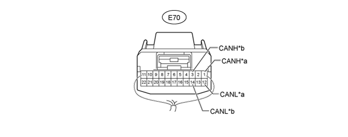
| *a | for No. 9 Junction Connector | *b | for Combination Meter Assembly (MS Bus) |
| No. 10 Junction Connector | Wiring Color | Connect to |
| E70-1 (CANH) | W | No. 9 junction connector |
| E70-12 (CANL) | R | |
| E70-3 (CANH) | LG | Combination meter assembly (MS bus) |
| E70-14 (CANL) | R |
NO. 1 CAN JUNCTION CONNECTOR (w/ Network Gateway ECU)
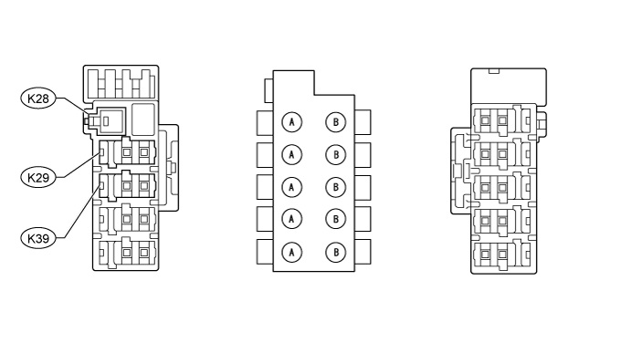
| Junction Connector A Side | Wiring Color (CANH Side) | Wiring Color (CANL Side) |
| Ground terminal (K28) | - | W-B |
| No. 7 junction connector (K29) | W | L |
| Suspension control ECU (K39)* | V | L |
NO. 2 CAN JUNCTION CONNECTOR
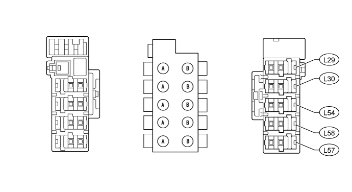
| Junction Connector B Side | Wiring Color (CANH Side) | Wiring Color (CANL Side) |
| No. 8 junction connector (L29) | LG | GR |
| No. 9 junction connector (L30) | Y | R |
| Power back door unit assembly (power back door ECU) (L54)*1 | V | R |
| No. 2 main body ECU (L57)*1 | LG | R |
| Tire pressure warning ECU and receiver (L58)*2 | G | R |
| TERMINALS OF CONNECTORS FOR JUNCTION CONNECTOR (CAN JUNCTION CONNECTOR) |
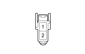
| Terminal No. | Symbol |
| 1 | CANH |
| 2 | CANL |
| CHECK DLC3 |

Disconnect the cable from the negative (-) battery terminal before measuring the resistances of the CAN main wire and CAN branch wire.
- NOTICE:
Measure the resistance according to the value(s) in the table below.
| Terminal No. (Symbol) | Wiring Color | Switch Condition | Specified Condition |
| E22-6 (CANH) - E22-14 (CANL) | G - B | Ignition switch off | 54 to 69 Ω |
| E22-6 (CANH) - E22-4 (CG) | G - W-B | Ignition switch off | 200 Ω or higher |
| E22-14 (CANL) - E22-4 (CG) | B - W-B | Ignition switch off | 200 Ω or higher |
| E22-6 (CANH) - E22-16 (BAT) | G - BE | Ignition switch off | 6 kΩ or higher |
| E22-14 (CANL) - E22-16 (BAT) | B - BE | Ignition switch off | 6 kΩ or higher |
| CHECK MASTER CYLINDER SOLENOID (SKID CONTROL ECU) |

Disconnect the A24 master cylinder solenoid (skid control ECU) connector.
Measure the resistance according to the value(s) in the table below.
| Terminal No. (Symbol) | Wiring Color | Switch Condition | Specified Condition |
| A24-11 (CANH) - A24-25 (CANL) | V - L | Ignition switch off | 54 to 69 Ω |
| A24-11 (CANH) - A24-1 (GND1) | V - W-B | Ignition switch off | 200 Ω or higher |
| A24-25 (CANL) - A24-1 (GND1) | L - W-B | Ignition switch off | 200 Ω or higher |
| A24-11 (CANH) - A24-2 (+BM1) | V - B | Ignition switch off | 6 kΩ or higher |
| A24-25 (CANL) - A24-2 (+BM1) | L - B | Ignition switch off | 6 kΩ or higher |
| CHECK AIR CONDITIONING AMPLIFIER ASSEMBLY (w/ Rear Air Conditioning System) |
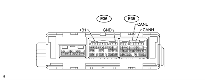
Measure the resistance according to the value(s) in the table below.
- HINT:
- Check from the rear of the connector while it is connected to the air conditioning amplifier.
| Terminal No. (Symbol) | Wiring Color | Switch Condition | Specified Condition |
| E35-3 (CANH) - E35-4 (CANL) | G - B | Ignition switch off | 54 to 69 Ω |
| E35-3 (CANH) - E36-1 (GND) | G - W-B | Ignition switch off | 200 Ω or higher |
| E35-4 (CANL) - E36-1 (GND) | B - W-B | Ignition switch off | 200 Ω or higher |
| E35-3 (CANH) - E36-6 (+B1) | G - R | Ignition switch off | 6 kΩ or higher |
| E35-4 (CANL) - E36-6 (+B1) | B - R | Ignition switch off | 6 kΩ or higher |
| CHECK AIR CONDITIONING AMPLIFIER ASSEMBLY (w/o Rear Air Conditioning System) |
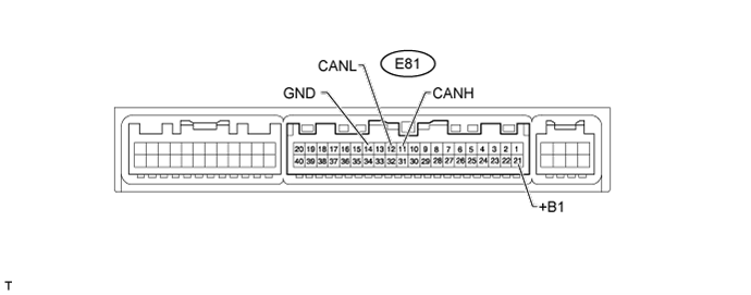
Disconnect the E81 air conditioning amplifier assembly connector.
Measure the resistance according to the value(s) in the table below.
| Terminal No. (Symbol) | Wiring Color | Switch Condition | Specified Condition |
| E81-11 (CANH) - E81-12 (CANL) | G - B | Ignition switch off | 54 to 69 Ω |
| E81-11 (CANH) - E81-14 (GND) | G - W-B | Ignition switch off | 200 Ω or higher |
| E81-12 (CANL) - E81-14 (GND) | B - W-B | Ignition switch off | 200 Ω or higher |
| E81-11 (CANH) - E81-21 (+B1) | G - R | Ignition switch off | 6 kΩ or higher |
| E81-12 (CANL) - E81-21 (+B1) | B - R | Ignition switch off | 6 kΩ or higher |
| CHECK ECM |
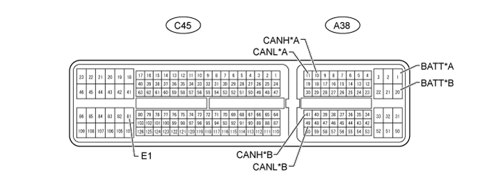
| *A | except 1VD-FTV | *B | for 1VD-FTV |
Disconnect the A38 and C45 ECM connectors.
Measure the resistance according to the value(s) in the table below.
| Terminal No. (Symbol) | Wiring Color | Switch Condition | Specified Condition |
| A38-10 (CANH) - A38-11 (CANL) | P - B | Ignition switch off | 108 to 132 Ω |
| A38-10 (CANH) - C45-81 (E1) | P - BR | Ignition switch off | 200 Ω or higher |
| A38-11 (CANL) - C45-81 (E1) | B - BR | Ignition switch off | 200 Ω or higher |
| A38-10 (CANH) - A38-1 (BATT) | P - L | Ignition switch off | 6 kΩ or higher |
| A38-11 (CANL) - A38-1 (BATT) | B - L | Ignition switch off | 6 kΩ or higher |
| Terminal No. (Symbol) | Wiring Color | Switch Condition | Specified Condition |
| A38-10 (CANH) - A38-11 (CANL) | P - B | Ignition switch off | 108 to 132 Ω |
| A38-10 (CANH) - C45-81 (E1) | P - W-B | Ignition switch off | 200 Ω or higher |
| A38-11 (CANL) - C45-81 (E1) | B - W-B | Ignition switch off | 200 Ω or higher |
| A38-10 (CANH) - A38-1 (BATT) | P - L | Ignition switch off | 6 kΩ or higher |
| A38-11 (CANL) - A38-1 (BATT) | B - L | Ignition switch off | 6 kΩ or higher |
| Terminal No. (Symbol) | Wiring Color | Switch Condition | Specified Condition |
| A38-41 (CANH) - A38-49 (CANL) | P - B | Ignition switch off | 108 to 132 Ω |
| A38-41 (CANH) - C45-81 (E1) | P - BR | Ignition switch off | 200 Ω or higher |
| A38-49 (CANL) - C45-81 (E1) | B - BR | Ignition switch off | 200 Ω or higher |
| A38-41 (CANH) - A38-20 (BATT) | P - L | Ignition switch off | 6 kΩ or higher |
| A38-49 (CANL) - A38-20 (BATT) | B - L | Ignition switch off | 6 kΩ or higher |
| CHECK MAIN BODY ECU (COWL SIDE JUNCTION BLOCK LH) |
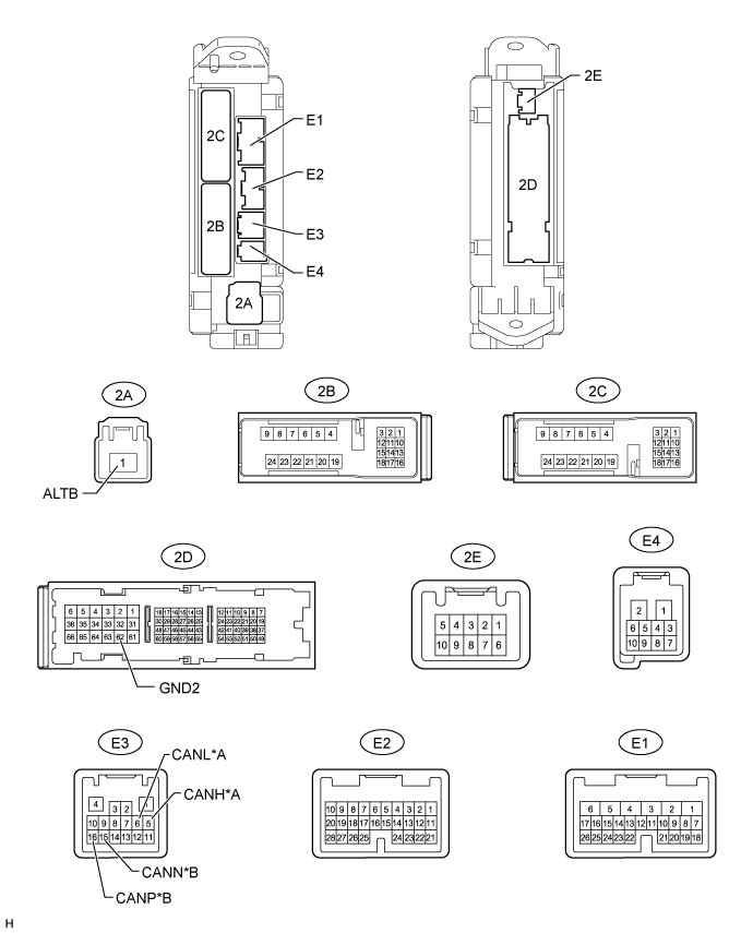
| *A | V Bus | *B | MS Bus |
Disconnect the E3, 2A and 2D main body ECU (cowl side junction block LH) connectors.
Measure the resistance according to the value(s) in the table below.
| Terminal No. (Symbol) | Wiring Color | Switch Condition | Specified Condition |
| E3-5 (CANH) - E3-6 (CANL) | SB - B | Ignition switch off | 54 to 69 Ω |
| E3-5 (CANH) - 2D-62 (GND2) | SB - W-B | Ignition switch off | 200 Ω or higher |
| E3-6 (CANL) - 2D-62 (GND2) | B - W-B | Ignition switch off | 200 Ω or higher |
| E3-5 (CANH) - 2A-1 (ALTB) | SB - B | Ignition switch off | 6 kΩ or higher |
| E3-6 (CANL) - 2A-1 (ALTB) | B - B | Ignition switch off | 6 kΩ or higher |
| Terminal No. (Symbol) | Wiring Color | Switch Condition | Specified Condition |
| E3-16 (CANP) - E3-15 (CANN) | GR - R | Ignition switch off | 108 to 132 Ω |
| E3-16 (CANP) - 2D-62 (GND2) | GR - W-B | Ignition switch off | 200 Ω or higher |
| E3-15 (CANN) - 2D-62 (GND2) | R - W-B | Ignition switch off | 200 Ω or higher |
| E3-16 (CANP) - 2A-1 (ALTB) | GR - B | Ignition switch off | 6 kΩ or higher |
| E3-15 (CANN) - 2A-1 (ALTB) | R - B | Ignition switch off | 6 kΩ or higher |
| CHECK COMBINATION METER ASSEMBLY |

| *A | V Bus | *B | MS Bus |
Disconnect the E7 combination meter assembly connector.
Measure the resistance according to the value(s) in the table below.
| Terminal No. (Symbol) | Wiring Color | Switch Condition | Specified Condition |
| E7-25 (CANH) - E7-26 (CANL) | V - B | Ignition switch off | 108 to 132 Ω |
| E7-25 (CANH) - E7-14 (EP) | V - W-B | Ignition switch off | 200 Ω or higher |
| E7-26 (CANL) - E7-14 (EP) | B - W-B | Ignition switch off | 200 Ω or higher |
| E7-25 (CANH) - E7-17 (B) | V - R | Ignition switch off | 6 kΩ or higher |
| E7-26 (CANL) - E7-17 (B) | B - R | Ignition switch off | 6 kΩ or higher |
| Terminal No. (Symbol) | Wiring Color | Switch Condition | Specified Condition |
| E7-1 (MPX+) - E7-2 (MPX-) | LG - R | Ignition switch off | 108 to 132 Ω |
| E7-1 (MPX+) - E7-14 (EP) | LG - W-B | Ignition switch off | 200 Ω or higher |
| E7-2 (MPX-) - E7-14 (EP) | R - W-B | Ignition switch off | 200 Ω or higher |
| E7-1 (MPX+) - E7-17 (B) | LG - R | Ignition switch off | 6 kΩ or higher |
| E7-2 (MPX-) - E7-17 (B) | R - R | Ignition switch off | 6 kΩ or higher |
| CHECK CENTER AIRBAG SENSOR ASSEMBLY (w/ Airbag System) |

Disconnect the E47 center airbag sensor assembly connector ().
Measure the resistance according to the value(s) in the table below.
| Terminal No. (Symbol) | Wiring Color | Switch Condition | Specified Condition |
| E47-13 (CANH) - E47-22 (CANL) | GR - B | Ignition switch off | 54 to 69 Ω |
| E47-13 (CANH) - E47-25 (E1) | GR - W-B | Ignition switch off | 200 Ω or higher |
| E47-22 (CANL) - E47-25 (E1) | B - W-B | Ignition switch off | 200 Ω or higher |
| E47-13 (CANH) - E22-16 (BAT) | GR - BE | Ignition switch off | 6 kΩ or higher |
| E47-22 (CANL) - E22-16 (BAT) | B - BE | Ignition switch off | 6 kΩ or higher |
| CHECK MULTI-MEDIA MODULE RECEIVER ASSEMBLY (w/ Navigation System) |
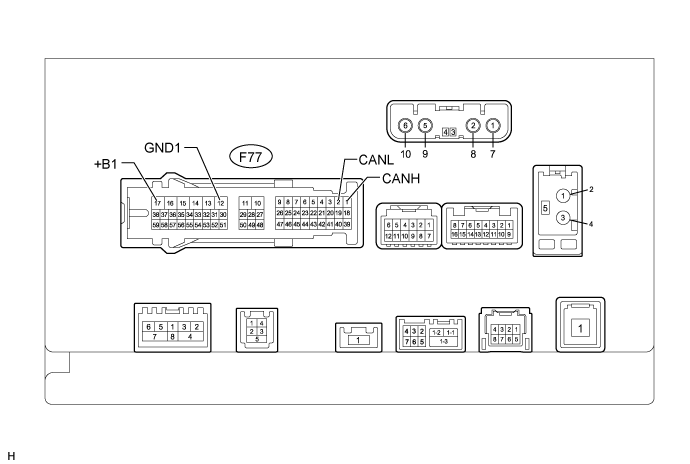
Disconnect the F77 multi-media module receiver assembly connector.
Measure the resistance according to the value(s) in the table below.
| Terminal No. (Symbol) | Wiring Color | Switch Condition | Specified Condition |
| F77-1 (CANH) - F77-2 (CANL) | P - B | Ignition switch off | 54 to 69 Ω |
| F77-1 (CANH) - F77-12 (GND1) | P - W-B | Ignition switch off | 200 Ω or higher |
| F77-2 (CANL) - F77-12 (GND1) | B - W-B | Ignition switch off | 200 Ω or higher |
| F77-1 (CANH) - F77-17 (+B1) | P - R | Ignition switch off | 6 kΩ or higher |
| F77-2 (CANL) - F77-17 (+B1) | B - R | Ignition switch off | 6 kΩ or higher |
| CHECK STEERING ANGLE SENSOR (w/ Vehicle Stability Control System) |
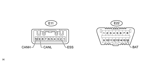
Disconnect the E11 steering angle sensor connector.
Measure the resistance according to the value(s) in the table below.
| Terminal No. (Symbol) | Wiring Color | Switch Condition | Specified Condition |
| E11-10 (CANH) - E11-9 (CANL) | GR - L | Ignition switch off | 54 to 69 Ω |
| E11-10 (CANH) - E11-2 (ESS) | GR - W-B | Ignition switch off | 200 Ω or higher |
| E11-9 (CANL) - E11-2 (ESS) | L - W-B | Ignition switch off | 200 Ω or higher |
| E11-10 (CANH) - E22-16 (BAT) | GR - BE | Ignition switch off | 6 kΩ or higher |
| E11-9 (CANL) - E22-16 (BAT) | L - BE | Ignition switch off | 6 kΩ or higher |
| CHECK YAW RATE SENSOR ASSEMBLY (w/ Vehicle Stability Control System) |

Disconnect the E50 yaw rate sensor assembly connector.
Measure the resistance according to the value(s) in the table below.
| Terminal No. (Symbol) | Wiring Color | Switch Condition | Specified Condition |
| E50-3 (CANH) - E50-2 (CANL) | BR - L | Ignition switch off | 54 to 69 Ω |
| E50-3 (CANH) - E50-1 (GND) | BR - W-B | Ignition switch off | 200 Ω or higher |
| E50-2 (CANL) - E50-1 (GND) | L - W-B | Ignition switch off | 200 Ω or higher |
| E50-3 (CANH) - E22-16 (BAT) | BR - BE | Ignition switch off | 6 kΩ or higher |
| E50-2 (CANL) - E22-16 (BAT) | L - BE | Ignition switch off | 6 kΩ or higher |
| CHECK SEAT BELT CONTROL ECU (w/ Pre-crash Safety System) |
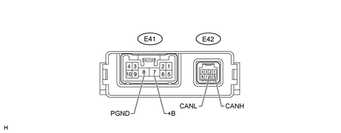
Disconnect the E41 and E42 seat belt control ECU connectors.
Measure the resistance according to the value(s) in the table below.
| Terminal No. (Symbol) | Wiring Color | Switch Condition | Specified Condition |
| E42-1 (CANH) - E42-2 (CANL) | G - L | Ignition switch off | 54 to 69 Ω |
| E42-1 (CANH) - E41-8 (PGND) | G - W-B | Ignition switch off | 200 Ω or higher |
| E42-2 (CANL) - E41-8 (PGND) | L - W-B | Ignition switch off | 200 Ω or higher |
| E42-1 (CANH) - E41-7 (+B) | G - R | Ignition switch off | 6 kΩ or higher |
| E42-2 (CANL) - E41-7 (+B) | L - R | Ignition switch off | 6 kΩ or higher |
| CHECK CLEARANCE WARNING ECU ASSEMBLY (w/ TOYOTA Parking Assist-sensor System and w/o Side Monitor System) |
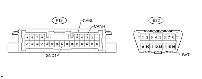
Disconnect the F12 clearance warning ECU assembly connector.
Measure the resistance according to the value(s) in the table below.
| Terminal No. (Symbol) | Wiring Color | Switch Condition | Specified Condition |
| F12-3 (CANH) - F12-5 (CANL) | V - L | Ignition switch off | 54 to 69 Ω |
| F12-3 (CANH) - F12-17 (GND1) | V - W-B | Ignition switch off | 200 Ω or higher |
| F12-5 (CANL) - F12-17 (GND1) | L - W-B | Ignition switch off | 200 Ω or higher |
| F12-3 (CANH) - E22-16 (BAT) | V - BE | Ignition switch off | 6 kΩ or higher |
| F12-5 (CANL) - E22-16 (BAT) | L - BE | Ignition switch off | 6 kΩ or higher |
| CHECK OUTER MIRROR CONTROL ECU ASSEMBLY (w/ Seat Memory) |

Disconnect the I17 and I18 outer mirror control ECU assembly connectors.
Measure the resistance according to the value(s) in the table below.
| Terminal No. (Symbol) | Wiring Color | Switch Condition | Specified Condition |
| I18-1 (CANH) - I18-21 (CANL) | BR - R | Ignition switch off | 54 to 69 Ω |
| I18-1 (CANH) - I17-9 (GND) | BR - W-B | Ignition switch off | 200 Ω or higher |
| I18-21 (CANL) - I17-9 (GND) | R - W-B | Ignition switch off | 200 Ω or higher |
| I18-1 (CANH) - I17-3 (B) | BR - R | Ignition switch off | 6 kΩ or higher |
| I18-21 (CANL) - I17-3 (B) | R - R | Ignition switch off | 6 kΩ or higher |
| CHECK MULTIPLEX TILT AND TELESCOPIC ECU (w/ Power Tilt and Power Telescopic Steering Column System) |

Disconnect the E27 multiplex tilt and telescopic ECU connector.
Measure the resistance according to the value(s) in the table below.
| Terminal No. (Symbol) | Wiring Color | Switch Condition | Specified Condition |
| E27-5 (CANP) - E27-14 (CANN) | P - R | Ignition switch off | 54 to 69 Ω |
| E27-5 (CANP) - E27-11 (GND) | P - W-B | Ignition switch off | 200 Ω or higher |
| E27-14 (CANN) - E27-11 (GND) | R - W-B | Ignition switch off | 200 Ω or higher |
| E27-5 (CANP) - E27-2 (+B) | P - L | Ignition switch off | 6 kΩ or higher |
| E27-14 (CANN) - E27-2 (+B) | R - L | Ignition switch off | 6 kΩ or higher |
| CHECK CERTIFICATION ECU (SMART KEY ECU ASSEMBLY) (w/ Entry and Start System) |
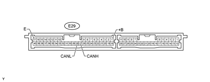
Disconnect the E29 certification ECU (smart key ECU assembly) connector.
Measure the resistance according to the value(s) in the table below.
| Terminal No. (Symbol) | Wiring Color | Switch Condition | Specified Condition |
| E29-27 (CANH) - E29-28 (CANL) | LG - R | Ignition switch off | 54 to 69 Ω |
| E29-27 (CANH) - E29-17 (E) | LG - W-B | Ignition switch off | 200 Ω or higher |
| E29-28 (CANL) - E29-17 (E) | R - W-B | Ignition switch off | 200 Ω or higher |
| E29-27 (CANH) - E29-1 (+B) | LG - B | Ignition switch off | 6 kΩ or higher |
| E29-28 (CANL) - E29-1 (+B) | R - B | Ignition switch off | 6 kΩ or higher |
| CHECK POSITION CONTROL ECU AND SWITCH (w/ Seat Memory) |

Disconnect the c14 and c15 position control ECU and switch connectors.
Measure the resistance according to the value(s) in the table below.
| Terminal No. (Symbol) | Wiring Color | Switch Condition | Specified Condition |
| c15-5 (MPX1) - c15-1 (MPX2) | V - R | Ignition switch off | 54 to 69 Ω |
| c15-5 (MPX1) - c14-1 (GND) | V - W-B | Ignition switch off | 200 Ω or higher |
| c15-1 (MPX2) - c14-1 (GND) | R - W-B | Ignition switch off | 200 Ω or higher |
| c15-5 (MPX1) - c14-5 (+B) | V - L | Ignition switch off | 6 kΩ or higher |
| c15-1 (MPX2) - c14-5 (+B) | R - L | Ignition switch off | 6 kΩ or higher |
| CHECK 4WD CONTROL ECU |
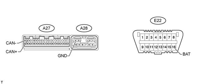
Disconnect the A27 and A28 4WD control ECU connectors.
Measure the resistance according to the value(s) in the table below.
| Terminal No. (Symbol) | Wiring Color | Switch Condition | Specified Condition |
| A27-19 (CAN+) - A27-20 (CAN-) | P - L | Ignition switch off | 54 to 69 Ω |
| A27-19 (CAN+) - A28-4 (GND) | P - W | Ignition switch off | 200 Ω or higher |
| A27-20 (CAN-) - A28-4 (GND) | L - W | Ignition switch off | 200 Ω or higher |
| A27-19 (CAN+) - E22-16 (BAT) | P - BE | Ignition switch off | 6 kΩ or higher |
| A27-20 (CAN-) - E22-16 (BAT) | L - BE | Ignition switch off | 6 kΩ or higher |
| CHECK NETWORK GATEWAY ECU (w/ Network Gateway ECU) |

| *A | V Bus | *B | Movement Control Bus |
Disconnect the E31 network gateway ECU connector.
Measure the resistance according to the value(s) in the table below.
| Terminal No. (Symbol) | Wiring Color | Switch Condition | Specified Condition |
| E31-16 (CA1H) - E31-15 (CA1L) | BR - B*1 BE - B*2 | Ignition switch off | 54 to 69 Ω |
| E31-16 (CA1H) - E31-4 (GND) | BR - W-B*1 BE - W-B*2 | Ignition switch off | 200 Ω or higher |
| E31-15 (CA1L) - E31-4 (GND) | B - W-B | Ignition switch off | 200 Ω or higher |
| E31-16 (CA1H) - E31-2 (BATT) | BR - R*1 BE - R*2 | Ignition switch off | 6 kΩ or higher |
| E31-15 (CA1L) - E31-2 (BATT) | B - R | Ignition switch off | 6 kΩ or higher |
| Terminal No. (Symbol) | Wiring Color | Switch Condition | Specified Condition |
| E31-13 (CA2H) - E31-12 (CA2L) | SB - L | Ignition switch off | 108 to 132 Ω |
| E31-13 (CA2H) - E31-4 (GND) | SB - W-B | Ignition switch off | 200 Ω or higher |
| E31-12 (CA2L) - E31-4 (GND) | L - W-B | Ignition switch off | 200 Ω or higher |
| E31-13 (CA2H) - E31-2 (BATT) | SB - R | Ignition switch off | 6 kΩ or higher |
| E31-12 (CA2L) - E31-2 (BATT) | L - R | Ignition switch off | 6 kΩ or higher |
| CHECK STEERING CONTROL ECU (w/ Variable Gear Ratio Steering System) |

Disconnect the E77 and E79 steering control ECU connectors.
Measure the resistance according to the value(s) in the table below.
| Terminal No. (Symbol) | Wiring Color | Switch Condition | Specified Condition |
| E79-9 (CANH) - E79-20 (CANL) | LG - L | Ignition switch off | 54 to 69 Ω |
| E79-9 (CANH) - E77-7 (PGND) | LG - W-B | Ignition switch off | 200 Ω or higher |
| E79-20 (CANL) - E77-7 (PGND) | L - W-B | Ignition switch off | 200 Ω or higher |
| E79-9 (CANH) - E77-10 (+BI) | LG - R | Ignition switch off | 6 kΩ or higher |
| E79-20 (CANL) - E77-10 (+BI) | L - R | Ignition switch off | 6 kΩ or higher |
| CHECK SUSPENSION CONTROL ECU (w/ Active Height Control Suspension) |

Disconnect the K34 suspension control ECU connector.
Measure the resistance according to the value(s) in the table below.
| Terminal No. (Symbol) | Wiring Color | Switch Condition | Specified Condition |
| K34-7 (CANH) - K34-8 (CANL) | V - L | Ignition switch off | 54 to 69 Ω |
| K34-7 (CANH) - K34-1 (GND) | V - W-B | Ignition switch off | 200 Ω or higher |
| K34-8 (CANL) - K34-1 (GND) | L - W-B | Ignition switch off | 200 Ω or higher |
| K34-7 (CANH) - K34-3 (BAT2) | V - R | Ignition switch off | 6 kΩ or higher |
| K34-8 (CANL) - K34-3 (BAT2) | L - R | Ignition switch off | 6 kΩ or higher |
| CHECK WINDSHIELD WIPER ECU (w/ Rain Sensor) |
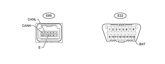
Disconnect the E85 windshield wiper ECU connector.
Measure the resistance according to the value(s) in the table below.
| Terminal No. (Symbol) | Wiring Color | Switch Condition | Specified Condition |
| E85-6 (CANH) - E85-5 (CANL) | LG - R | Ignition switch off | 54 to 69 Ω |
| E85-6 (CANH) - E85-10 (E) | LG - W-B | Ignition switch off | 200 Ω or higher |
| E85-5 (CANL) - E85-10 (E) | R - W-B | Ignition switch off | 200 Ω or higher |
| E85-6 (CANH) - E22-16 (BAT) | LG - BE | Ignition switch off | 6 kΩ or higher |
| E85-5 (CANL) - E22-16 (BAT) | R - BE | Ignition switch off | 6 kΩ or higher |
| CHECK PARKING ASSIST ECU (w/ Side Monitor System) |

Disconnect the F75 and F76 parking assist ECU connectors.
Measure the resistance according to the value(s) in the table below.
| Terminal No. (Symbol) | Wiring Color | Switch Condition | Specified Condition |
| F76-40 (CANH) - F76-39 (CANL) | V - L | Ignition switch off | 54 to 69 Ω |
| F76-40 (CANH) - F75-4 (GND1) | V - W-B | Ignition switch off | 200 Ω or higher |
| F76-39 (CANL) - F75-4 (GND1) | L - W-B | Ignition switch off | 200 Ω or higher |
| F76-40 (CANH) - F75-1 (+B) | V - L | Ignition switch off | 6 kΩ or higher |
| F76-39 (CANL) - F75-1 (+B) | L - L | Ignition switch off | 6 kΩ or higher |
| CHECK DISTANCE CONTROL ECU ASSEMBLY (w/ Dynamic Radar Cruise Control System) |

Disconnect the E108 distance control ECU assembly connector.
Measure the resistance according to the value(s) in the table below.
| Terminal No. (Symbol) | Wiring Color | Switch Condition | Specified Condition |
| E108-8 (CANH) - E108-9 (CANL) | SB - L | Ignition switch off | 54 to 69 Ω |
| E108-8 (CANH) - E108-12 (GND) | SB - BR | Ignition switch off | 200 Ω or higher |
| E108-9 (CANL) - E108-12 (GND) | L - BR | Ignition switch off | 200 Ω or higher |
| E108-8 (CANH) - E22-16 (BAT) | SB - BE | Ignition switch off | 6 kΩ or higher |
| E108-9 (CANL) - E22-16 (BAT) | L - BE | Ignition switch off | 6 kΩ or higher |
| CHECK POWER BACK DOOR UNIT ASSEMBLY (POWER BACK DOOR ECU) (w/ Power Back Door System) |

Disconnect the L52 power back door unit assembly (power back door ECU) connector.
Measure the resistance according to the value(s) in the table below.
| Terminal No. (Symbol) | Wiring Color | Switch Condition | Specified Condition |
| L52-6 (MPX1) - L52-5 (MPX2) | V - R | Ignition switch off | 54 to 69 Ω |
| L52-6 (MPX1) - L52-11 (GND) | V - W-B | Ignition switch off | 200 Ω or higher |
| L52-5 (MPX2) - L52-11 (GND) | R - W-B | Ignition switch off | 200 Ω or higher |
| L52-6 (MPX1) - L52-10 (ECUB) | V - R | Ignition switch off | 6 kΩ or higher |
| L52-5 (MPX2) - L52-10 (ECUB) | R - R | Ignition switch off | 6 kΩ or higher |
| CHECK TIRE PRESSURE WARNING ECU AND RECEIVER (w/ Tire Pressure Warning System) |

Disconnect the L60 tire pressure warning ECU and receiver connector.
Measure the resistance according to the value(s) in the table below.
| Terminal No. (Symbol) | Wiring Color | Switch Condition | Specified Condition |
| L63-3 (CP1) - L63-6 (CN1) | W - B | Ignition switch off | 54 to 69 Ω |
| L63-3 (CP1) - L63-4 (GN1) | W - G | Ignition switch off | 200 Ω or higher |
| L63-6 (CN1) - L63-4 (GN1) | B - G | Ignition switch off | 200 Ω or higher |
| L63-3 (CP1) - E22-16 (BAT) | W - BE | Ignition switch off | 6 kΩ or higher |
| L63-6 (CN1) - E22-16 (BAT) | B - BE | Ignition switch off | 6 kΩ or higher |
| CHECK NO. 2 MAIN BODY ECU (w/ Power Back Door System) |

Disconnect the L50 No. 2 main body ECU connector.
Measure the resistance according to the value(s) in the table below.
| Terminal No. (Symbol) | Wiring Color | Switch Condition | Specified Condition |
| L50-11 (MPX+) - L50-12 (MPX-) | LG - R | Ignition switch off | 54 to 69 Ω |
| L50-11 (MPX+) - L50-7 (GND) | LG - W-B | Ignition switch off | 200 Ω or higher |
| L50-12 (MPX-) - L50-7 (GND) | R - W-B | Ignition switch off | 200 Ω or higher |
| L50-11 (MPX+) - L50-14 (BECU) | LG - R | Ignition switch off | 6 kΩ or higher |
| L50-12 (MPX-) - L50-14 (BECU) | R - R | Ignition switch off | 6 kΩ or higher |
| CHECK HEADLIGHT SWIVEL ECU ASSEMBLY (w/ Dynamic Headlight Auto Leveling) |

Disconnect the E101 headlight swivel ECU assembly connector.
Measure the resistance according to the value(s) in the table below.
| Terminal No. (Symbol) | Wiring Color | Switch Condition | Specified Condition |
| E101-12 (MPX1) - E101-13 (MPX2) | LG - B | Ignition switch off | 54 to 69 Ω |
| E101-12 (MPX1) - E101-22 (E1) | LG - W-B | Ignition switch off | 200 Ω or higher |
| E101-13 (MPX2) - E101-22 (E1) | B - W-B | Ignition switch off | 200 Ω or higher |
| E101-12 (MPX1) - E22-16 (BAT) | LG - BE | Ignition switch off | 6 kΩ or higher |
| E101-13 (MPX2) - E22-16 (BAT) | B - BE | Ignition switch off | 6 kΩ or higher |
| CHECK POWER STEERING ECU ASSEMBLY (for 1VD-FTV with DPF) |
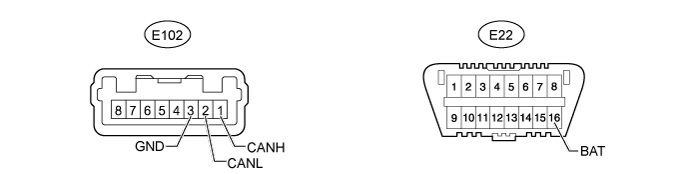
Disconnect the E102 power steering ECU assembly connector.
Measure the resistance according to the value(s) in the table below.
| Terminal No. (Symbol) | Wiring Color | Switch Condition | Specified Condition |
| E102-1 (CANH) - E102-2 (CANL) | LG - L | Ignition switch off | 54 to 69 Ω |
| E102-1 (CANH) - E102-3 (GND) | LG - W-B | Ignition switch off | 200 Ω or higher |
| E102-2 (CANL) - E102-3 (GND) | L - W-B | Ignition switch off | 200 Ω or higher |
| E102-1 (CANH) - E22-16 (BAT) | LG - BE | Ignition switch off | 6 kΩ or higher |
| E102-2 (CANL) - E22-16 (BAT) | L - BE | Ignition switch off | 6 kΩ or higher |
| CHECK ACCESSORY BUS BUFFER |
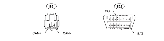
Disconnect the E6 accessory bus buffer connector.
Measure the resistance according to the value(s) in the table below.
| Terminal No. (Symbol) | Wiring Color | Switch Condition | Specified Condition |
| E6-1 (CAN+) - E6-2 (CAN-) | V - R | Ignition switch off | 54 to 69 Ω |
| E6-1 (CAN+) - E22-4 (CG) | V - W-B | Ignition switch off | 200 Ω or higher |
| E6-2 (CAN-) - E22-4 (CG) | R - W-B | Ignition switch off | 200 Ω or higher |
| E6-1 (CAN+) - E22-16 (BAT) | V - BE | Ignition switch off | 6 kΩ or higher |
| E6-2 (CAN-) - E22-16 (BAT) | R - BE | Ignition switch off | 6 kΩ or higher |