Land Cruiser URJ200 URJ202 GRJ200 VDJ200 - NETWORKING
CAN COMMUNICATION SYSTEM (for LHD) - HOW TO PROCEED WITH TROUBLESHOOTING
| IMPORTANT POINT CONCERNING TROUBLESHOOTING |
Disconnect the cable from the negative (-) battery terminal before measuring the resistances of the main wire and the branch wire.
- CAUTION:
- For vehicles with an SRS system
- Wait at least 90 seconds after disconnecting the cable from the negative (-) battery terminal to disable the SRS system.
- NOTICE:
- HINT:
| 1.VEHICLE BROUGHT TO WORKSHOP |
|
| 2.INSPECT BATTERY VOLTAGE |
- Standard voltage:
- 11 to 14 V
If the voltage is below 11 V, recharge or replace the battery before proceeding.
|
| 3.CHECK FOR DTC* |
Using the intelligent tester, check for all DTCs.
- NOTICE:
|
| 4.CHECK INSTALLED SYSTEMS (ECUS AND SENSORS) THAT USE CAN COMMUNICATION |
Based on the vehicle equipment and specifications, confirm the systems that use CAN communication ().
|
| 5.CHECK FOR OPEN CIRCUIT IN DLC3 CAN BRANCH WIRE AND V BUS CIRCUIT CAN MAIN WIRE AND CHECK FOR SHORT CIRCUIT (CANH - CANL) |
Disconnect the cable from the negative (-) battery terminal before measuring the resistances of the CAN main wire and CAN branch wire.
- NOTICE:
- When disconnecting the cable, some systems need to be initialized after the cable is reconnected ().
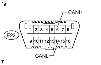
Measure the resistance according to the value(s) in the table below.
- Standard Resistance:
Tester Connection Switch Condition Specified Condition Proceed to E22-6 (CANH) - E22-14 (CANL) Ignition switch off OK (54 to 69 Ω) A E22-6 (CANH) - E22-14 (CANL) Ignition switch off NG (70 Ω or higher) B E22-6 (CANH) - E22-14 (CANL) Ignition switch off NG (Below 53 Ω) C
| *a | Front view of DLC3 |
|
| ||||
|
| ||||
|
| 6.CHECK FOR SHORT TO +B IN CAN V BUS (CANH, CANL - BAT) |
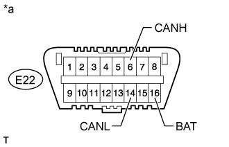
Measure the resistance according to the value(s) in the table below.
- Standard Resistance:
Tester Connection Switch Condition Specified Condition E22-6 (CANH) - E22-16 (BAT) Ignition switch off 6 kΩ or higher E22-14 (CANL) - E22-16 (BAT) Ignition switch off 6 kΩ or higher
| *a | Front view of DLC3 |
|
| ||||
|
| 7.CHECK FOR SHORT TO GND IN CAN V BUS (CANH, CANL - CG) |

Measure the resistance according to the value(s) in the table below.
- Standard Resistance:
Tester Connection Switch Condition Specified Condition E22-6 (CANH) - E22-4 (CG) Ignition switch off 200 Ω or higher E22-14 (CANL) - E22-4 (CG) Ignition switch off 200 Ω or higher
| *a | Front view of DLC3 |
|
| ||||
|
| 8.CHECK ECUS CONNECTED TO CAN BUS* |
Connect the cable to the negative (-) battery terminal.
- NOTICE:
- When disconnecting the cable, some systems need to be initialized after the cable is reconnected ().
Select "Bus Check" from "System Select" ().
Wait 1 minute and then check the display of the connected ECUs and sensors.
| Result | Proceed to |
| All ECUs and sensors connected to CAN communication system are displayed on screen (CAN bus circuit currently normal) | A |
| Except for the main body ECU (cowl side junction block LH), no ECUs connected to the MS bus are displayed. The main body ECU (cowl side junction block LH) outputs the MS bus trouble code (U1002) (MS bus main wire open or short malfunction). | B |
| No ECUs connected to the MS bus are displayed (the branch wire between the main body ECU (cowl side junction block LH) and V bus circuit is open). | C |
| Except for the network gateway ECU, no ECUs connected to the movement control bus are displayed.* The network gateway ECU outputs the movement control bus trouble code (U1002) (movement control bus main wire open or short malfunction). | D |
| No ECUs connected to the movement control bus are displayed (the branch wire between the network gateway ECU and movement control bus is open).* | E |
| An ECU or sensor that should be connected to the CAN communication system is not displayed (the ECU or sensor branch wire is open). | F |
| An ECU or sensor that should be connected to the CAN communication system is not displayed or display is intermittent during check (the ECU or sensor branch wire is open on one side). | G |
- NOTICE:
- ECUs and sensors that are not present will not be displayed. Be careful not to mistake them for communication stop malfunctions.
- HINT:
|
| ||||
|
| ||||
|
| ||||
|
| ||||
|
| ||||
|
| ||||
|
| 9.CHECK COMMUNICATION MALFUNCTION DTC (PAST DTC CHECK)* |
Select "Bus Check" from "System Select" ().
Write down all of the DTCs stored in each ECU.
- HINT:
| Result | Proceed to |
| An ECU connected to the V bus main wire has stored a communication trouble code (V bus main wire past malfunction). | A |
| The main body ECU (cowl side junction block LH) outputs the MS bus trouble code (U1002) (MS bus past malfunction). | B |
| The main body ECU (cowl side junction block LH) outputs a trouble code other than MS bus trouble code (U1002) (past malfunction of ECU branch wire connected to MS bus). | C |
| The network gateway ECU outputs a movement control bus trouble code (U1002) (movement control bus past malfunction).* | D |
| The network gateway ECU outputs a trouble code other than movement control bus trouble code (U1002) (past malfunction of branch wire connected to movement control bus).* | E |
|
| ||||
|
| ||||
|
| ||||
|
| ||||
|
| 10.CHECK DTC COMBINATION TABLE (V BUS CIRCUIT BRANCH WIRE OPEN PAST MALFUNCTION) |
Based on the combination of output CAN communication system DTCs, determine which ECUs and sensors have a communication stop malfunction ().
|
| 11.PERFORM MALFUNCTION SIMULATION TEST (V1 BUS CIRCUIT CAN MAIN WIRE PAST MALFUNCTION)* |
Using the intelligent tester, clear all DTCs.
Perform a malfunction simulation test on all harnesses and connectors related to the V bus CAN main wire.
Check the DTCs that were output as a result of the malfunction simulation test. Then determine the malfunctioning area.
|
| 12.ADJUST, REPAIR AND REPLACE |
|
| 13.CONFIRMATION TEST |
| ||||
|
|---|