Land Cruiser URJ200 URJ202 GRJ200 VDJ200 - PARK ASSIST / MONITORING
SIDE MONITOR SYSTEM - CALIBRATION
| ADJUST SIDE MONITOR SYSTEM |
This side monitor system can be set from the diagnostic screen of the multi-display assembly.
If the following operations are performed, it is necessary to perform adjustments and checks on the diagnostic screen.
| Part Name | Operation | Adjustment Item | Proceed to |
| Steering sensor | Removal and installation of the Steering angle sensor Removal and installation of the connector of the Steering angle sensor Replacement |
Steering angle neutral point | |
| Steering angle setting | |||
| Multi-media module receiver assembly | Replacement | Vehicle contract setting | |
| Parking assist ECU | Replacement | Parking assist ECU initialization | |
| Suspension, tires, etc. | The vehicle height changes because of suspension or tire replacement | Rear television camera optical axis (Camera position setting) | |
| Side television camera optical axis (Camera position setting) | Procedure 1 | ||
| Side television camera assembly | Replacement Installation angle of the side television camera changes because of the removal and installation of the side television camera, etc. |
Side television camera optical axis (Camera position setting) | Procedure 1 |
| Outer rear view mirror assembly | Replacement | Side television camera optical axis (Camera position setting) | Procedure 1 |
- NOTICE:
- After the engine switch is turned off, the multi-media module receiver assembly requires approximately 60 seconds to record various types of memory and settings. As a result, after turning the engine switch off, wait a minute or more before disconnecting the cable from the negative (-) battery terminal.
- HINT:
- The adjustment values stored while performing side monitor system calibration are stored in the parking assist ECU.
| SIDE CAMERA SETTING (Procedure 1) |
- HINT:
- Be sure to check for DTCs before performing this procedure ().
Preparation for adjustment
Park the vehicle with the steering wheel centered.
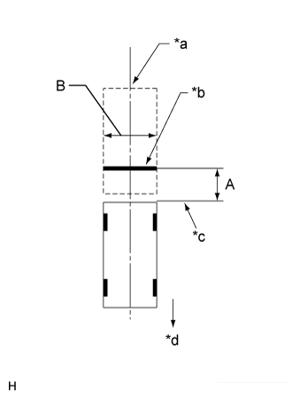
Set a target bar for optical axis adjustment of the rear television camera.
- HINT:
- Only when adjusting the optical axis of the camera, create a target bar for adjustment.
- Dimension:
Area Specification A 825 to 835 mm (2.71 to 2.74 ft.) B 1995 to 2005 mm (6.45 to 6.58 ft.)
| *a | Vehicle Center |
| *b | Target Bar for Back Camera Adjustment |
| *c | Vehicle End |
| *d | Front Side |
- HINT:
Set a target bar for optical axis adjustment of the side television camera.
- HINT:
- Only when adjusting the optical axis of the camera, create a target bar for adjustment.
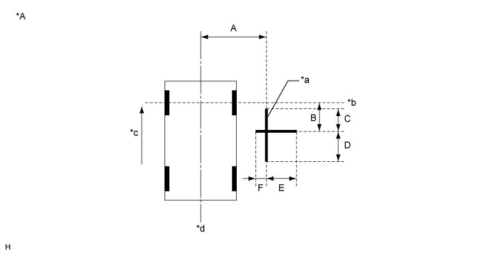
| *A | for LHD | - | - |
| *a | Target Bar for Side Camera Adjustment | *b | Front Wheel Axis |
| *c | Front Side | *d | Vehicle Center |

| *A | for RHD | - | - |
| *a | Target Bar for Side Camera Adjustment | *b | Front Wheel Axis |
| *c | Front Side | *d | Vehicle Center |
- Dimension:
A B C D E F 1183 mm
(3.88 ft.)1181 mm
(3.87 ft.)500 mm
(1.64 ft.)500 mm
(1.64 ft.)500 mm
(1.64 ft.)180 mm
(7.09 in.)
- HINT:
- Target bars for side camera adjustment should be made with 2 pieces of 2.5 cm wide tape; one piece should be 100 cm (3.28 ft.) (C+D) and the other should be 68 cm (2.23 ft.) (E+F) long. Check the tape color on the multi-media module receiver assembly and choose a tape color which can be easily seen.
Start diagnostic mode ().
- NOTICE:
- Alignment must be performed with the engine running. For this reason, it is necessary to apply the parking brake, depress the brake pedal, and move the shift lever into the P position, and to exercise all other necessary caution to ensure that the vehicle does not begin moving unexpectedly.
- HINT:
- The displayed items may differ depending on vehicle specifications.
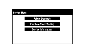
Select "Function Check/Setting" on the [Service Menu] screen.
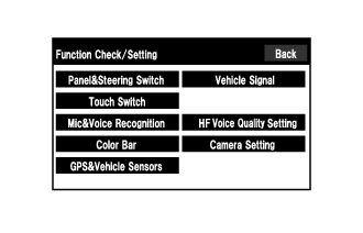
Select "Camera Setting" on the [Function Check/Setting] screen.

Select "Side Camera Setting" on the [Mode Setting] screen.
- HINT:
- To select a grayed out item, select and hold the item for 2 seconds or more.
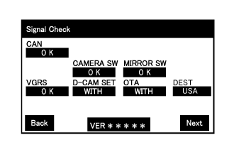
Select "Next" on the [Signal Check] screen.
- NOTICE:
- HINT:
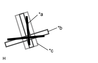
Side Camera Position Setting:
- HINT:
- Colors used on the [Side Camera Position Setting] screen
| *a | Target Adjustment Bar for Side Camera Position Setting |
| *b | Red Frame |
| *c | Yellow Frame |
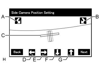
Perform the roll angle adjustment.
Perform the vertical and horizontal position adjustment.
Select "Next" to display [Side Verify Mode].
Side Verify Mode:

Check that the red cross and the target adjustment bar are aligned.
- HINT:
- If they are not aligned, select "Back" and perform [Side Camera Position Setting] again.
Select "Next" to display [Side Camera Signal Check].
Side Camera Signal Check:
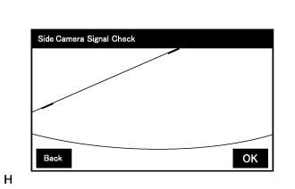
Select "OK" to store the side camera aiming adjustment value and change the screen to the [Service Menu] screen.
- HINT:
Finish diagnostic mode ().