Navigation System Rds-Tmc Signal Circuit Between Radio Receiver And Navigation Ecu
DESCRIPTION
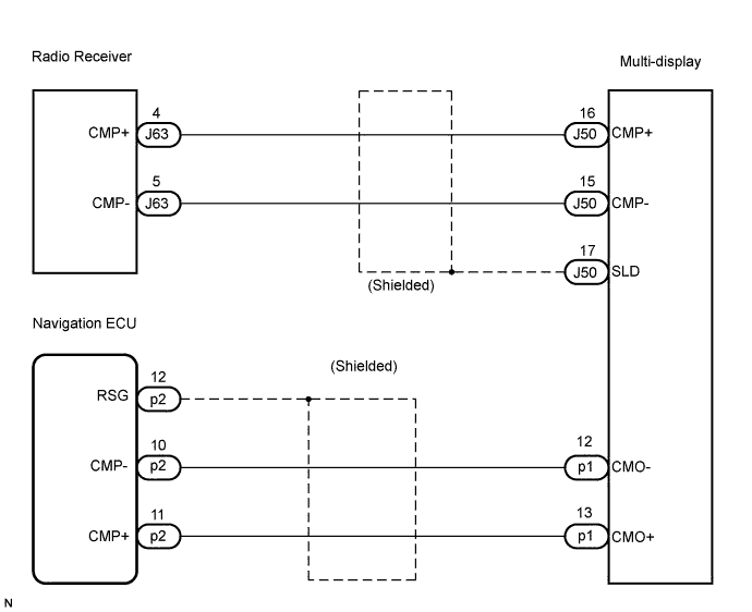
WIRING DIAGRAM
INSPECTION PROCEDURE
CHECK HARNESS AND CONNECTOR (MULTI-DISPLAY - RADIO RECEIVER)
CHECK HARNESS AND CONNECTOR (NAVIGATION ECU - MULTI-DISPLAY)
NAVIGATION SYSTEM - RDS-TMC Signal Circuit between Radio Receiver and Navigation ECU |
DESCRIPTION
Traffic information received by the radio receiver is transmitted to the navigation ECU via this circuit.If an open or short occurs in this circuit, RDS-TMC information will not be updated or the RDS-TMC will not operate normally.
WIRING DIAGRAM
INSPECTION PROCEDURE
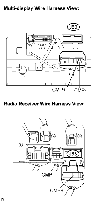
| 1.CHECK HARNESS AND CONNECTOR (MULTI-DISPLAY - RADIO RECEIVER) |
Disconnect the multi-display connector J50 and radio receiver connector J63.
Measure the resistance according to the value(s) in the table below.
- Standard resistance:
Tester connection
| Condition
| Specified condition
|
CMP+ - CMP+
| Always
| Below 1 Ω
|
CMP- - CMP-
| Always
| Below 1 Ω
|
CMP+ - Body ground
| Always
| 10 kΩ or higher
|
CMP- - Body ground
| Always
| 10 kΩ or higher
|
| | REPAIR OR REPLACE HARNESS OR CONNECTOR |
|
|
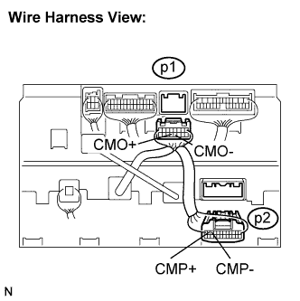
| 2.CHECK HARNESS AND CONNECTOR (NAVIGATION ECU - MULTI-DISPLAY) |
Disconnect the navigation ECU connector p2 and multi-display connector p1.
Measure the resistance according to the value(s) in the table below.
- Standard resistance:
Tester connection
| Condition
| Specified condition
|
CMO- - CMP-
| Always
| Below 1 Ω
|
CMO+ - CMP+
| Always
| Below 1 Ω
|
CMO- - Body ground
| Always
| 10 kΩ or higher
|
CMO+ - Body ground
| Always
| 10 kΩ or higher
|
| | REPAIR OR REPLACE HARNESS OR CONNECTOR |
|
|
| OK |
|
|
|
| PROCEED TO NEXT CIRCUIT INSPECTION SHOWN IN PROBLEM SYMPTOMS TABLE |
|