DESCRIPTION
WIRING DIAGRAM
INSPECTION PROCEDURE
INSPECT STEREO COMPONENT AMPLIFIER
CHECK OPERATION
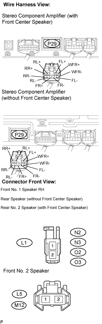
CHECK HARNESS AND CONNECTOR
INSPECT FRONT NO. 1 SPEAKER (LEFT HAND)
CONFIRM MODEL
INSPECT REAR NO. 2 SPEAKER (RIGHT HAND)
INSPECT REAR NO. 2 SPEAKER (LEFT HAND)
INSPECT REAR NO. 3 SPEAKER (RIGHT HAND)
INSPECT REAR NO. 3 SPEAKER (LEFT HAND)
INSPECT REAR STEREO COMPONENT SPEAKER (LEFT HAND)
INSPECT REAR STEREO COMPONENT SPEAKER (RIGHT HAND)
INSPECT FRONT STEREO COMPONENT SPEAKER
INSPECT WOOFER BOX SPEAKER
CHECK HARNESS AND CONNECTOR
INSPECT FRONT NO. 1 SPEAKER (RIGHT HAND)
INSPECT FRONT NO. 2 SPEAKER (RIGHT HAND)
INSPECT FRONT NO. 2 SPEAKER (LEFT HAND)
INSPECT FRONT NO. 3 SPEAKER (RIGHT HAND)
INSPECT FRONT NO. 3 SPEAKER (LEFT HAND)
CONFIRM MODEL
INSPECT REAR NO. 2 SPEAKER (RIGHT HAND)
INSPECT REAR NO. 2 SPEAKER (LEFT HAND)
INSPECT REAR SPEAKER (RIGHT HAND)
INSPECT REAR SPEAKER (LEFT HAND)
DTC 74-40 Short in Speaker Circuit |
DESCRIPTION
DTC No.
| DTC Detection Condition
| Trouble Area
|
74-40
| A short is detected in the speaker output circuit.
| - Wire harness
- Speaker
- Stereo component amplifier
|
This circuit has a fail-safe function.- When a short in the speaker circuit is detected, all sound output is stopped.
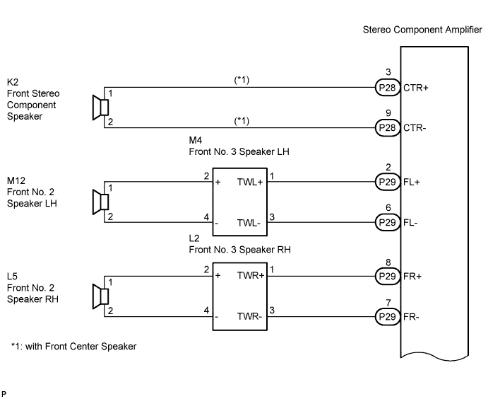
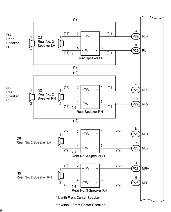
WIRING DIAGRAM
INSPECTION PROCEDURE
- HINT:
- After the inspection is completed, clear the DTCs.
| 1.INSPECT STEREO COMPONENT AMPLIFIER |
Disconnect the stereo component amplifier connectors P29 and P28.
Clear the DTCs and recheck for DTCs.
Check if DTC 74-40 is output.
- OK:
- DTC 74-40 is not output.
| | REPLACE STEREO COMPONENT AMPLIFIER |
|
|
Reconnect the stereo component amplifier connector P29.
Check if DTC 74-40 is output.
- OK:
- DTC 74-40 is not output.
| 3.CHECK HARNESS AND CONNECTOR |
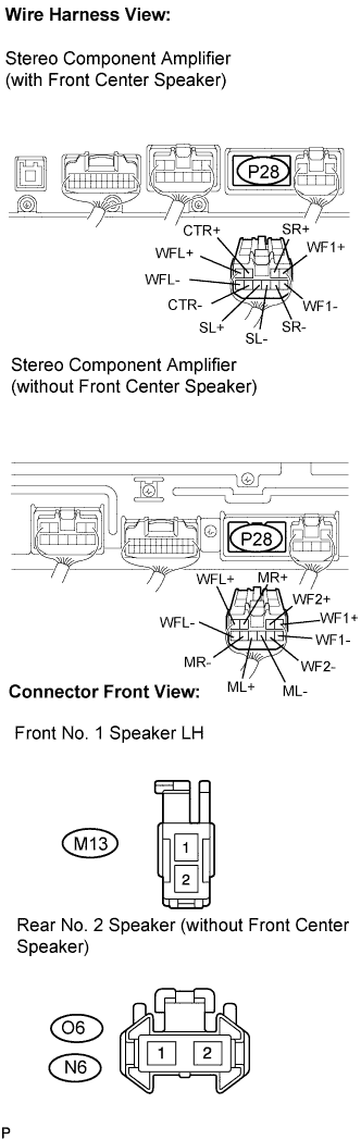
Disconnect the connectors shown in the illustration from the stereo component amplifier and speakers.

|
Measure the resistance according to the value(s) in the table below.
- Standard resistance:
Tester connection
| Condition
| Specified condition
|
CTR+ - Body ground (*1)
| Always
| 10 kΩ or higher
|
CTR- - Body ground (*1)
| Always
| 10 kΩ or higher
|
ML+ - Body ground (*2)
| Always
| 10 kΩ or higher
|
ML- - Body ground (*2)
| Always
| 10 kΩ or higher
|
O4-2 - Body ground (*2)
| Always
| 10 kΩ or higher
|
O4-4 - Body ground (*2)
| Always
| 10 kΩ or higher
|
MR+ - Body ground (*2)
| Always
| 10 kΩ or higher
|
MR- - Body ground (*2)
| Always
| 10 kΩ or higher
|
N4-2 - Body ground (*2)
| Always
| 10 kΩ or higher
|
N4-4 - Body ground (*2)
| Always
| 10 kΩ or higher
|
SL+ - Body ground (*1)
| Always
| 10 kΩ or higher
|
SL- - Body ground (*1)
| Always
| 10 kΩ or higher
|
SR+ - Body ground (*1)
| Always
| 10 kΩ or higher
|
SR- - Body ground (*1)
| Always
| 10 kΩ or higher
|
WFL+ - Body ground
| Always
| 10 kΩ or higher
|
WFL- - Body ground
| Always
| 10 kΩ or higher
|
WF2+ - Body ground (*2)
| Always
| 10 kΩ or higher
|
WF2- - Body ground (*2)
| Always
| 10 kΩ or higher
|
WF1+ - Body ground
| Always
| 10 kΩ or higher
|
WF1- - Body ground
| Always
| 10 kΩ or higher
|
*1: with Front Center Speaker
*2: without Front Center Speaker
| | REPAIR OR REPLACE HARNESS OR CONNECTOR |
|
|
| 4.INSPECT FRONT NO. 1 SPEAKER (LEFT HAND) |
Resistance check.
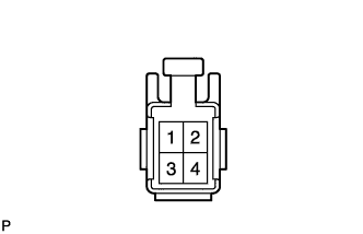
Measure the resistance between the terminals of the speaker.
- Standard resistance:
- with Front Center Speaker:
- 6 to 10 Ω
- without Front Center Speaker:
- Approximately 4 Ω
| | REPLACE FRONT NO. 1 SPEAKER (LEFT HAND) |
|
|
- Result:
Result
| Proceed to
|
without Front Center Speaker
| A
|
with Front Center Speaker
| B
|
| 6.INSPECT REAR NO. 2 SPEAKER (RIGHT HAND) |
Reconnect the stereo component amplifier connector and rear No. 2 speaker connector.
Check that audio sound can be heard from the speaker.
- OK:
- Audio sound can be heard.
| | REPLACE REAR NO. 2 SPEAKER (RIGHT HAND) |
|
|
| 7.INSPECT REAR NO. 2 SPEAKER (LEFT HAND) |
Reconnect the stereo component amplifier connector and rear No. 2 speaker connector.
Check that audio sound can be heard from the speaker.
- OK:
- Audio sound can be heard.
| | REPLACE REAR NO. 2 SPEAKER (LEFT HAND) |
|
|
| 8.INSPECT REAR NO. 3 SPEAKER (RIGHT HAND) |
Reconnect the stereo component amplifier connector and rear No. 3 speaker connector.
Check that audio sound can be heard from the speaker.
- OK:
- Audio sound can be heard.
| | REPLACE REAR NO. 3 SPEAKER (RIGHT HAND) |
|
|
| 9.INSPECT REAR NO. 3 SPEAKER (LEFT HAND) |
Reconnect the stereo component amplifier connector and rear No. 3 speaker connector.
Check that audio sound can be heard from the speaker.
- OK:
- Audio sound can be heard.
| NG |
|
|
|
| REPLACE REAR NO. 3 SPEAKER (LEFT HAND) |
|
| 10.INSPECT REAR STEREO COMPONENT SPEAKER (LEFT HAND) |
Reconnect the stereo component amplifier connector and rear stereo component speaker connector.
Check that audio sound can be heard from the speaker.
- OK:
- Audio sound can be heard.
| | REPLACE REAR STEREO COMPONENT SPEAKER (LEFT HAND) |
|
|
| 11.INSPECT REAR STEREO COMPONENT SPEAKER (RIGHT HAND) |
Reconnect the stereo component amplifier connector and rear stereo component speaker connector.
Check that audio sound can be heard from the speaker.
- OK:
- Audio sound can be heard.
| | REPLACE REAR STEREO COMPONENT SPEAKER (RIGHT HAND) |
|
|
| 12.INSPECT FRONT STEREO COMPONENT SPEAKER |
Resistance check.
Measure the resistance between the terminals of the speaker.
- Standard resistance:
- 7 to 9 Ω
| | REPLACE FRONT STEREO COMPONENT SPEAKER |
|
|
| 13.INSPECT WOOFER BOX SPEAKER |
Resistance check.
Measure the resistance according to the value(s) in the table below.
- NOTICE:
- The speaker should not be removed for checking.
- Standard resistance:
- with Front Center Speaker:
Tester connection
| Condition
| Specified condition
|
3 - 4
| Always
| 7 to 8.6 Ω
|
- without Front Center Speaker:
Tester connection
| Condition
| Specified condition
|
1 - 3
| Always
| Approximately 2 Ω
|
2 - 4
| Always
| Approximately 2 Ω
|
| | REPLACE WOOFER BOX SPEAKER |
|
|
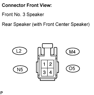
| 14.CHECK HARNESS AND CONNECTOR |
Disconnect the connectors shown in the illustration from the stereo component amplifier and speakers.
Measure the resistance according to the value(s) in the table below.
- Standard resistance:
Tester connection
| Condition
| Specified condition
|
FL+ - Body ground
| Always
| 10 kΩ or higher
|
FL- - Body ground
| Always
| 10 kΩ or higher
|
M4-2 - Body ground
| Always
| 10 kΩ or higher
|
M4-4 - Body ground
| Always
| 10 kΩ or higher
|
FR+ - Body ground
| Always
| 10 kΩ or higher
|
FR- - Body ground
| Always
| 10 kΩ or higher
|
L2-2 - Body ground
| Always
| 10 kΩ or higher
|
L2-4 - Body ground
| Always
| 10 kΩ or higher
|
RL+ - Body ground
| Always
| 10 kΩ or higher
|
RL- - Body ground
| Always
| 10 kΩ or higher
|
O5-2 - Body ground (*1)
| Always
| 10 kΩ or higher
|
O5-4 - Body ground (*1)
| Always
| 10 kΩ or higher
|
RR+ - Body ground
| Always
| 10 kΩ or higher
|
RR- - Body ground
| Always
| 10 kΩ or higher
|
N5-2 - Body ground (*1)
| Always
| 10 kΩ or higher
|
N5-4 - Body ground (*1)
| Always
| 10 kΩ or higher
|
WFR+ - Body ground
| Always
| 10 kΩ or higher
|
WFR- - Body ground
| Always
| 10 kΩ or higher
|
*1: with Front Center Speaker
| | REPAIR OR REPLACE HARNESS OR CONNECTOR |
|
|
| 15.INSPECT FRONT NO. 1 SPEAKER (RIGHT HAND) |
Resistance check.
Measure the resistance between the terminals of the speaker.
- Standard resistance:
- with Front Center Speaker:
- 6 to 10 Ω
- without Front Center Speaker:
- Approximately 4 Ω
| | REPLACE FRONT NO. 1 SPEAKER (RIGHT HAND) |
|
|
| 16.INSPECT FRONT NO. 2 SPEAKER (RIGHT HAND) |
Reconnect the stereo component amplifier connector and front No. 2 speaker connector.
Check that audio sound can be heard from the speaker.
- OK:
- Audio sound can be heard.
| | REPLACE FRONT NO. 2 SPEAKER (RIGHT HAND) |
|
|
| 17.INSPECT FRONT NO. 2 SPEAKER (LEFT HAND) |
Reconnect the stereo component amplifier connector and front No. 2 speaker connector.
Check that audio sound can be heard from the speaker.
- OK:
- Audio sound can be heard.
| | REPLACE FRONT NO. 2 SPEAKER (LEFT HAND) |
|
|
| 18.INSPECT FRONT NO. 3 SPEAKER (RIGHT HAND) |
Reconnect the stereo component amplifier connector and front No. 3 speaker connector.
Check that audio sound can be heard from the speaker.
- OK:
- Audio sound can be heard.
| | REPLACE FRONT NO. 3 SPEAKER (RIGHT HAND) |
|
|
| 19.INSPECT FRONT NO. 3 SPEAKER (LEFT HAND) |
Reconnect the stereo component amplifier connector and front No. 3 speaker connector.
Check that audio sound can be heard from the speaker.
- OK:
- Audio sound can be heard.
| | REPLACE FRONT NO. 3 SPEAKER (LEFT HAND) |
|
|
- Result:
Result
| Proceed to
|
with Front Center Speaker
| A
|
without Front Center Speaker
| B
|
| 21.INSPECT REAR NO. 2 SPEAKER (RIGHT HAND) |
Reconnect the stereo component amplifier connector and rear No. 2 speaker connector.
Check that audio sound can be heard from the speaker.
- OK:
- Audio sound can be heard.
| | REPLACE REAR NO. 2 SPEAKER (RIGHT HAND) |
|
|
| 22.INSPECT REAR NO. 2 SPEAKER (LEFT HAND) |
Reconnect the stereo component amplifier connector and rear No. 2 speaker connector.
Check that audio sound can be heard from the speaker.
- OK:
- Audio sound can be heard.
| | REPLACE REAR NO. 2 SPEAKER (LEFT HAND) |
|
|
| 23.INSPECT REAR SPEAKER (RIGHT HAND) |
Reconnect the stereo component amplifier connector and rear speaker connector.
Check that audio sound can be heard from the speaker.
- OK:
- Audio sound can be heard.
| | REPLACE REAR SPEAKER (RIGHT HAND) |
|
|
| OK |
|
|
|
| REPLACE REAR SPEAKER (LEFT HAND) |
|
| 24.INSPECT REAR SPEAKER (LEFT HAND) |
Resistance check.
Measure the resistance between the terminals of the speaker.
- Standard resistance:
- Approximately 4 Ω
| | REPLACE REAR SPEAKER (LEFT HAND) |
|
|
| OK |
|
|
|
| REPLACE REAR SPEAKER (RIGHT HAND) |
|