Meter / Gauge System Tachometer Malfunction
Meter. Lexus Is250, Is220D. Gse20 Ale20
DESCRIPTION
WIRING DIAGRAM
INSPECTION PROCEDURE
PERFORM ACTIVE TEST BY INTELLIGENT TESTER
READ VALUE OF INTELLIGENT TESTER (ENGINE SPEED SIGNAL)
READ VALUE OF INTELLIGENT TESTER (ENGINE SPEED SIGNAL)
CHECK HARNESS AND CONNECTOR (COMBINATION METER - ECM)
INSPECT COMBINATION METER ASSEMBLY
METER / GAUGE SYSTEM - Tachometer Malfunction |
DESCRIPTION
- The meter CPU receives engine speed signals from the ECM in this circuit.
- The ECM transmits engine speed signals as pulses to the meter CPU.
- The meter CPU calculates the engine speed converting 3 pulses to 1 revolution.
WIRING DIAGRAM
INSPECTION PROCEDURE
| 1.PERFORM ACTIVE TEST BY INTELLIGENT TESTER |
Connect the intelligent tester to the DLC3.
Turn the engine switch on (IG).
Turn the tester ON.
Enter the following menus: Diagnosis / Body / Combination Meter / Active Test.
Check the values by referring to the table below.
Combination Meter:Item
| Test Details
| Diagnostic Note
|
Tacho Meter Operation
| 0, 1,000, 2,000, 3,000, 4,000, 5,000, 6,000, 7,000, 8,000 (rpm)
| -
|
- OK:
- Needle indication is normal.
| | REPLACE COMBINATION METER ASSEMBLY |
|
|
| 2.READ VALUE OF INTELLIGENT TESTER (ENGINE SPEED SIGNAL) |
Connect the intelligent tester to the DLC3.
Turn the engine switch on (IG).
Turn the tester ON.
Enter the following menus: Diagnosis / Body / Combination Meter / Data Test.
Check the values by referring to the table below.
Combination Meter:Item
| Measurement Item/Range (Display)
| Normal Condition
| Diagnostic Note
|
Engine RPM
| Engine speed/Min.: 0 rpm, Max.: 12,750 rpm
| Almost same as actual engine speed (When engine is running)
| -
|
- OK:
- Engine speed displayed on the tester is almost the same as the actual engine speed.
| OK |
|
|
|
| REPLACE COMBINATION METER ASSEMBLY |
|
| 3.READ VALUE OF INTELLIGENT TESTER (ENGINE SPEED SIGNAL) |
Connect the intelligent tester to the DLC3.
Turn the engine switch on (IG).
Turn the tester ON.
Enter the following menus: Diagnosis / Power Train / Engine / Data Test.
Check the values by referring to the table below.
Engine:Item
| Measurement Item/Range (Display)
| Normal Condition
| Diagnostic Note
|
Engine Spd
| Engine speed/Min.: 0 rpm, Max.: 16,383 rpm
| Almost same as actual engine speed (When engine is running)
| -
|
| | GO TO ENGINE CONTROL SYSTEM |
|
|
| 4.CHECK HARNESS AND CONNECTOR (COMBINATION METER - ECM) |
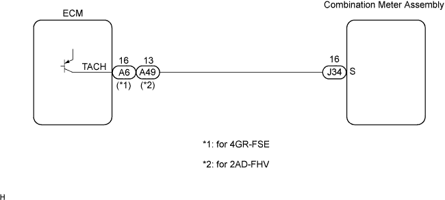
Disconnect the A6(*1) / E59 (*2) and J34 connectors.
Measure the resistance according to the value(s) in the table below.
- Standard resistance:
Tester Connection
| Condition
| Specified Condition
|
A6-16 (TACH) (*1) - J34-16 (S)
| Always
| Below 1 Ω
|
A6-16 (TACH) (*1) - Body ground
| Always
| 10 kΩ or higher
|
A49-13 (TACH) (*2) - J34-16
| Always
| Below 1 Ω
|
A49-13 (TACH) (*2) - Body ground
| Always
| 10 kΩ or higher
|
*1: for 4GR-FSE
*2: for 2AD-FHV
| | REPAIR OR REPLACE HARNESS OR CONNECTOR |
|
|
| 5.INSPECT COMBINATION METER ASSEMBLY |
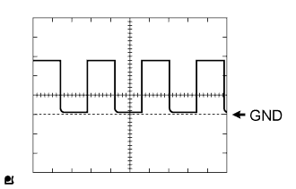
Check the input signal waveform.
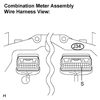
Remove the combination meter with the connector still connected.
Connect the oscilloscope to terminal J34-16 (S) and body ground.
Start the engine.
Check the signal waveform according to the condition(s) in the table below.
Item
| Condition
|
Tool setting
| 5 V/DIV., 10 ms./DIV.
|
Vehicle condition
| Engine idle speed
|
- OK:
- The waveform is displayed as shown in the illustration.
| | REPLACE COMBINATION METER ASSEMBLY |
|
|