Lighting System -- System Description |
The system representations shown below are intended to show concept of operation, and may not precisely reflect the construction of the system on the vehicle.
| AUTOMATIC LIGHT CONTROL SYSTEM |
General
When the light control switch is in the AUTO position, the automatic light control system detects ambient light levels and controls the headlights, parking lights, taillights, marker lights, and license plate lights.
- The main body ECU RH controls this system.
- The headlight dimmer switch includes the tilt and telescopic switch, fog switch, turn switch, dimmer switch, and light control switch. The headlight dimmer switch signals are received by the windshield wiper switch assembly, and the windshield wiper switch assembly forwards these signals to the main body ECU RH using the Body Electronics Area Network (BEAN).
- A direct headlight backup link (HEAD) exists between the windshield wiper switch assembly and the main body ECU RH. If this link is grounded, the headlights will illuminate.
- Ambient light levels are detected by the light control sensor that is integrated in the air conditioning system's solar sensor. This signal is received directly by the main body ECU RH (cowl side junction block RH).
- The dimmer circuit in the combination meter controls the ground for the panel illumination.
- The combination meter bases the control of the panel illumination on signals received from the light control rheostat, and other inputs.
- The main body ECU RH controls the taillights and panel illumination using the tail relay that is built into the main body ECU LH (cowl side junction block LH).
The main body ECU RH controls the low beam illumination using the HEAD LP relay.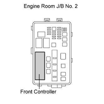
- The front controller operates the high beams using the HEAD HI relay that is built into the front controller.
- The front controller operates the front parking lights using the FR TAIL relay that is built into the front controller (engine room No. 2 relay block).
- The front controller operates the front fog lights using the FR FOG relay that is built into the front controller (engine room No. 2 relay block).
- The main body ECU RH controls this system.
| MANUAL LIGHT CONTROL SYSTEM |
The function of the system is similar to the automatic light control system, except the system is controlled according to the driver's inputs.
| BI-FUNCTION |
The models with HID (High Intensity Discharge) headlights have a Bi-function.
This Bi-function increases the upper illumination area of the discharge bulb (LO/HI beam) when the HI beam is turned on.- If the LO beam is selected, the upper illumination area of the discharge bulb is blocked by a shade and only the lower illumination area is used. If the HI beam is selected, the headlight solenoid slides the shutter (shade) down to allow use of the upper illumination area, thus increasing the illumination area and improving visibility when the HI beam is on.
- The headlight solenoid is operated by the power that is supplied to the high beam bulbs.
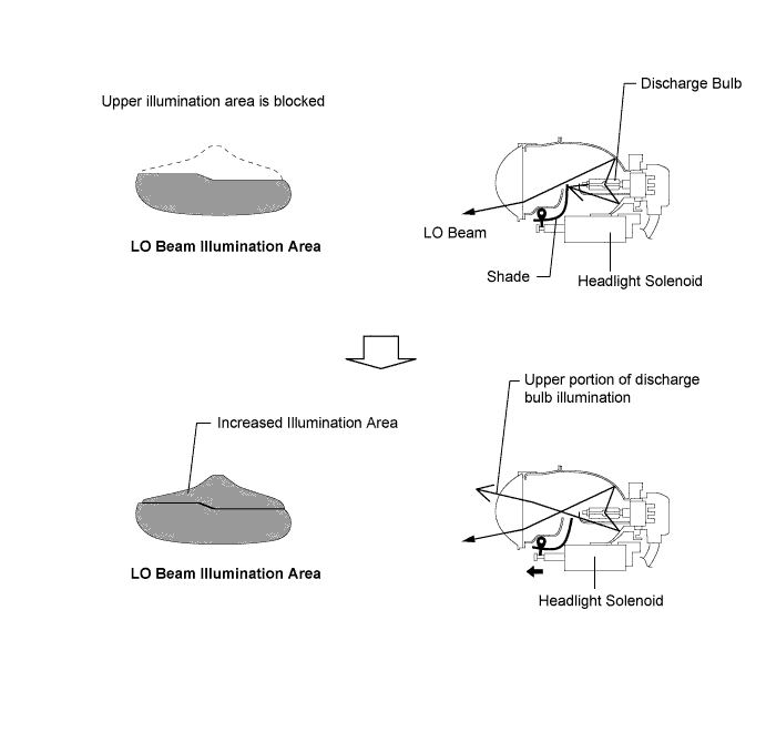
- If the LO beam is selected, the upper illumination area of the discharge bulb is blocked by a shade and only the lower illumination area is used. If the HI beam is selected, the headlight solenoid slides the shutter (shade) down to allow use of the upper illumination area, thus increasing the illumination area and improving visibility when the HI beam is on.
| HID HEADLIGHT SYSTEM |
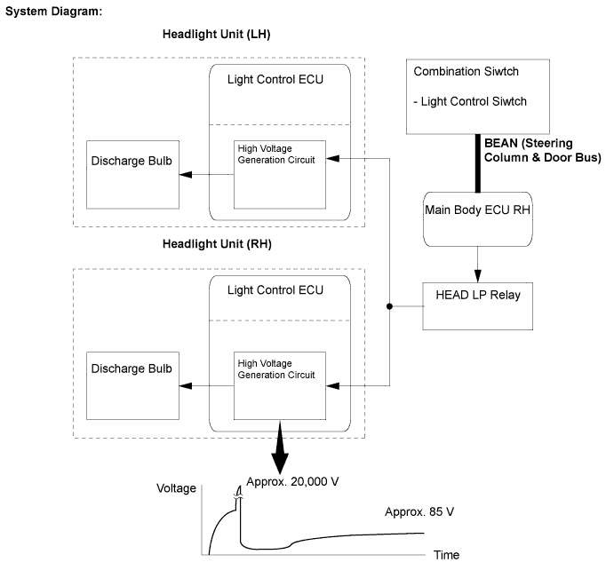
This system consists primarily of the light control switch, windshield wiper SW assembly, main body ECU RH, HEAD LP relay, discharge bulbs, and light control ECUs.
- The main body ECU RH controls the low beam illumination using the HEAD LP relay.
- The BEAN network is used for communications.
- A HEAD backup link exists between the windshield wiper switch and the main body ECU RH.
- The light control ECUs transform the voltage that is input from the battery to a high voltage of up to 20,000 V and apply this voltage to the discharge bulbs in order to illuminate them.
- A fail-safe function is provided as a countermeasure against the high voltage that is generated in case that a problem occurs in the headlight system.
- NOTICE:
- For safety reasons, do not attempt to measure the voltage output from a light control ECU.
- The main body ECU RH controls the low beam illumination using the HEAD LP relay.
| MANUAL HEADLIGHT BEAM LEVEL CONTROL SYSTEM |
When the vehicle posture changes in accordance with the number (weight) of passengers and volume of luggage, this system enable the adjustment of the LO beam level (6-step) of the headlights manually to appropriate level based on the position of the headlight beam level control switch.
- The beam level of the headlights can be adjusted by the headlight level actuators that are integrated in the headlight units.
- A headlight beam level control switch is provided to allow the driver to control this system.
- The beam level of the headlights can be adjusted by the headlight level actuators that are integrated in the headlight units.
| AUTOMATIC HEADLIGHT BEAM LEVEL CONTROL SYSTEM |
When the headlights are on, the automatic headlight beam level control system operates the headlight level actuators in accordance with the movement of the vehicle.
- The automatic headlight beam level control system mainly consists of the AFS ECU, front height control sensor, rear height control sensor, and two headlight level actuators. The AFS ECU controls the system.
- The ECU detects the movement of the suspension from the front and rear height control sensors, and the vehicle speed from the front RH and LH speed sensors.
- The ECU then controls the headlight level actuator based on this information, in order to change the headlight reflector angle.
- The AFS ECU controls both the level control system and the intelligent AFS system.
- The automatic headlight beam level control system mainly consists of the AFS ECU, front height control sensor, rear height control sensor, and two headlight level actuators. The AFS ECU controls the system.
Initial Set Control
- When the AFS ECU detects a vehicle speed of 1 km/h (0.6 mph) and the engine is running at 400 rpm or more, the ECU executes the initial setting of the stepper motors.
- When the AFS ECU detects a vehicle speed of 1 km/h (0.6 mph) and the engine is running at 400 rpm or more, the ECU executes the initial setting of the stepper motors.
Fail-Safe Function
- If the AFS ECU detects a malfunction in the automatic headlight beam level control system, the AFS ECU effects fail-safe control. At the same time, the AFS ECU flashes the AFS OFF indicator light in order to inform the driver of the problem.
- If the AFS ECU detects a malfunction in the automatic headlight beam level control system, the AFS ECU effects fail-safe control. At the same time, the AFS ECU flashes the AFS OFF indicator light in order to inform the driver of the problem.
| INTELLIGENT AFS (ADAPTIVE FRONT-LIGHTING SYSTEM) |
An intelligent AFS (Adaptive Front-lighting System) is used in order to turn the LO/HI (discharge) beam toward the inside of the cornering direction.
The separate (incandescent) HI beam illumination is not controlled by this system.
Swivel Angle Range: Driving Condition RHD Models LHD Models Headlight Unit Headlight Unit Left Right Left Right Right Turn 0° Fixed 0 to 15°(to Right) 0° Fixed 0 to 5°(to Right) Left Turn 0 to 5°(to Left) 0° Fixed 0 to 15°(to Left) 0° Fixed - This system consists of the two headlight units for LO/HI beam (discharge illumination), the AFS ECU, two headlight swivel actuators, steering angle sensor and front speed sensors. The AFS ECU controls this system.
- The AFS ECU also controls the automatic headlight beam level control system.
- The system does not control the incandescent HI beam illumination.
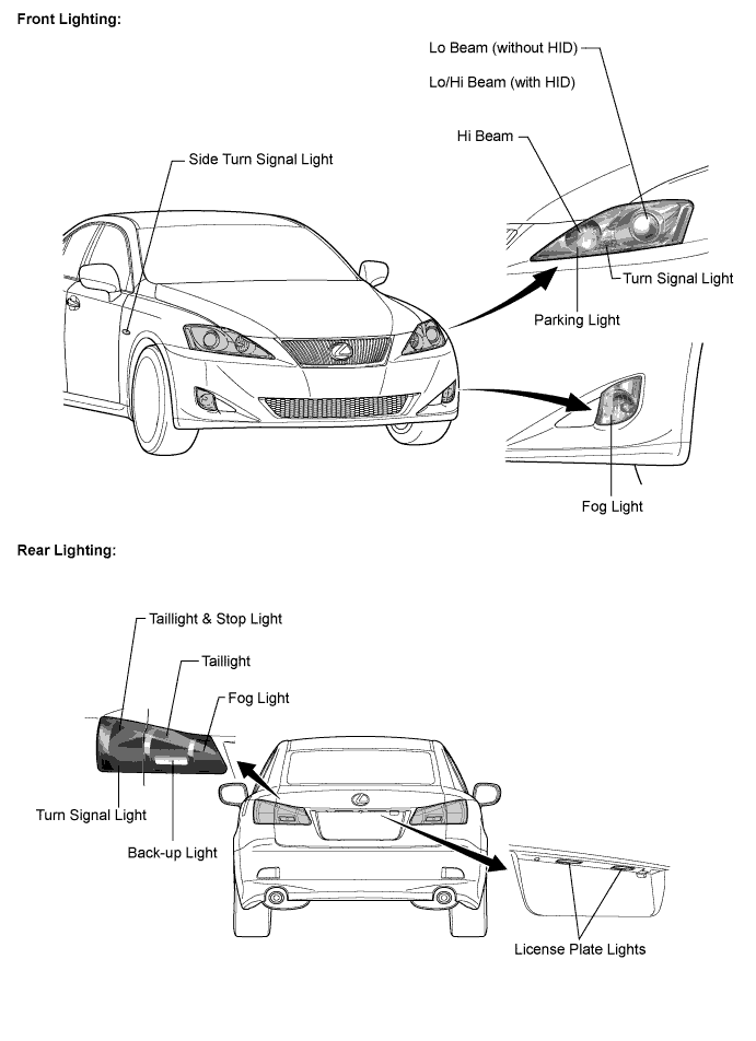
- The lights controlled by this system (LO/HI beam) are shown in the Front Lighting illustration.
- This system consists of the two headlight units for LO/HI beam (discharge illumination), the AFS ECU, two headlight swivel actuators, steering angle sensor and front speed sensors. The AFS ECU controls this system.
The AFS ECU performs intelligent AFS control when all the following conditions are fulfilled.
- Engine is running.
- Vehicle is moving* forward at 10 km/h (6 mph) or more, or stopped.
- Steering angle* is 7.5° or more.
- Headlight LO/HI beam operates.
- Daytime running light system is not operating.
- AFS ON/OFF condition is ON.
*: Swivel angle change is accordance with the vehicle speed and steering angle. - The minimum vehicle speed to change the swivel is 10 km/h (6 mph) if the steering angle is wide.
- The minimum steering angle to change the swivel is 7.5° if the vehicle speed is high.
- Engine is running.
The AFS ECU calculates the target lighting angle of the LO/HI beam based on the steering angle and the vehicle speed. Then, it actuates the headlight swivel actuators in order to attain the target lighting angle.
The operation angle of the headlights is detected by the position (number of steps) of the stepper motor in the headlight swivel actuator.
| DAYTIME RUNNING LIGHT SYSTEM |
The daytime running light system is designed to automatically illuminate the headlights (Lo beam), parking lights, taillights and license plate lights during the daytime to keep the car highly visible to other vehicles.
- The main body ECU RH and front controller control this system. The main body ECU RH transmits a turn ON signal to the front controller, and the front controller illuminates the front parking lights. The main body ECU RH causes the HEAD LP relay to illuminate the headlights (low beam). The main body ECU RH also causes its tail relay to illuminate the taillights and license plate lights.
- This system is enabled when the conditions given below are met:
- Power source: IG-ON
- Engine speed signal input (engine running condition)
- Light control switch OFF or AUTO position (if headlight-on control is not being performed by the automatic light control)
- HINT:
- The lights that are controlled are shown in the Front Lighting and Rear Lighting illustrations.
- The main body ECU RH and front controller control this system. The main body ECU RH transmits a turn ON signal to the front controller, and the front controller illuminates the front parking lights. The main body ECU RH causes the HEAD LP relay to illuminate the headlights (low beam). The main body ECU RH also causes its tail relay to illuminate the taillights and license plate lights.
| ILLUMINATED ENTRY SYSTEM |
General
The illuminated entry system has the seven control functions shown in the following chart:
*1: Illuminates for approximately 15 seconds, fades out (fades out over three seconds).Control Operation Outline Lights that Operate Actuation Area-linked Turn ON When the key enters any actuation area around the doors, the front and rear seat illumination turns on. - Front Seat Illumination
- Rear Seat Illumination
- Door Mirror Foot Lights
Transmitter-linked Turn ON When the following condition is satisfied, the lights that operate turn on. - Any door is unlocked using the transmitter.
- Front Seat Illumination
- Rear Seat Illumination
- Footwell Lights*3
- Door Mirror Foot Lights
Door Open-linked Turn ON The lights that operate turn on when the following condition is satisfied. - Any door is opened.
- Engine Switch Illumination
- Front Interior Light
- Rear Interior Light
- Scuff Plate Lights
- Door Courtesy Lights
- Footwell Lights*3
Door Close-linded Turn OFF*1 When the following condition is satisfied, the lights that operate turn off. - All doors are closed.
- Front Seat Illumination
- Rear Seat Illumination
- Engine Switch Illumination
- Front Interior Lights
- Rear Interior Light
- Scuff Plate Lights
- Door Courtesy Lights
- Footwell Lights*3
- Door Mirror Foot Lights
Door Lock-linked Turn OFF*2 When the following condition is satisfied, the lights that operate turn off. - All doors are locked.
Power Source-linked Turn ON When the following condition is satisfied, the shift illumination turns on. - Power source is changed from OFF to ACC or IG-ON.
- Shift Illumination
Turn OFF*2 When the following condition is satisfied, the lights that operate turn off. - Power source is changed from OFF to ACC or IG-ON.
- Front Seat Illumination
- Rear Seat Illumination
- Engine Switch Illumination
- Door Courtesy Lights
- Footwell Lights*3
- Door Mirror Foot Lights
Battery Saving Turn OFF When the following two conditions have been satisfied, these lights turn off. - A key is not in the actuation area.
- There are no changes in the condition of the doors for 20 minutes.
- Front Seat Illumination
- Rear Seat Illumination
- Engine Switch Illumination
- Front Interior Lights
- Rear Interior Lights
- Scuff Plate Lights
- Door Courtesy Lights
- Footwell Lights*3
*2: Stops the illumination, starts to fade out immediately (fades out over three seconds).
*3: The footwell lights go off when the light control rheostat is adjusted to the minimum level.- Front Seat Illumination
| TURN SIGNALS |
The turn signals are front, rear and side lights that can be used to indicate a change of vehicle direction.
- The turn signal switch signals are received by the windshield wiper switch assembly (combination switch ECU).
- The main body ECU LH operates the turn signal flasher.
- The turn signal flasher operates the signal lights.
- The bulb for the side turn signal light is integrated into the side turn signal light unit.
If the bulb fails, the side turn signal light unit must be replaced as an assembly.
- HINT:
- The lights that are controlled are shown in the Front Lighting and Rear Lighting illustrations.
- The turn signal switch signals are received by the windshield wiper switch assembly (combination switch ECU).
| HEADLIGHT CLEANER SYSTEM |
Some vehicles are provided with a headlight cleaner system. More details on the headlight cleaner system operation can be found in the wiper section.