INSTALL MAIN BODY ECU (COWL SIDE JUNCTION BLOCK LH) (for LHD)
INSTALL LOWER INSTRUMENT PANEL FINISH PANEL SUB-ASSEMBLY (for LHD)
INSTALL NO.1 INSTRUMENT PANEL UNDER COVER SUB-ASSEMBLY (for LHD)
INSTALL LOWER INSTRUMENT PANEL FINISH PANEL SUB-ASSEMBLY (for RHD)
INSTALL NO. 1 INSTRUMENT PANEL UNDER COVER SUB-ASSEMBLY (for RHD)
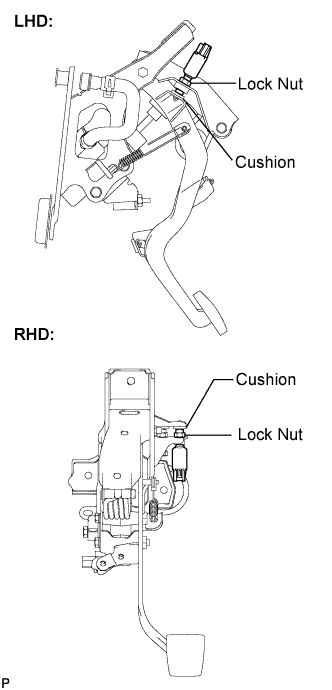
Clutch Switch -- Installation |
| 1. INSTALL CLUTCH SWITCH ASSEMBLY |
Fully loosen the lock nut of the clutch switch assembly.
Adjust the clutch switch until the threaded portion makes gentle contact with the cushion. Tighten the lock nut and verify the contact of the switch threaded portion with the cushion.
- Torque:
- 15.7 N*m{160 kgf*cm, 12 ft.*lbf}
 |
Connect the connector.
| 2. INSTALL MAIN BODY ECU (COWL SIDE JUNCTION BLOCK LH) (for LHD) |
Install the main body ECU (cowl side junction block LH) with the 2 nuts.
- Torque:
- 8.0 N*m{82 kgf*cm, 71 in.*lbf}
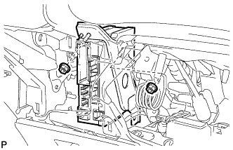 |
Connect all connectors.
| 3. INSTALL LOWER INSTRUMENT PANEL FINISH PANEL SUB-ASSEMBLY (for LHD) |
Connect the connectors.
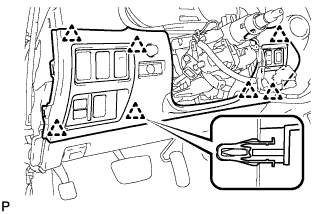 |
Engage the 7 clips and install the lower instrument panel finish panel sub-assembly.
| 4. INSTALL NO.1 INSTRUMENT PANEL UNDER COVER SUB-ASSEMBLY (for LHD) |
Connect the connectors.
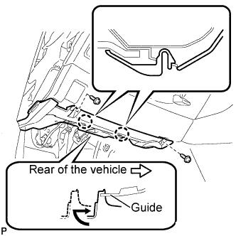 |
Insert the No. 1 instrument panel under cover sub-assembly into the guide as shown in the illustration.
Engage the 2 claws.
Install the No. 1 instrument panel under cover sub-assembly with the 2 screws <E>.
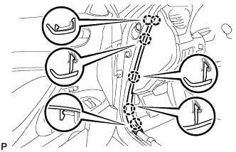
| 5. INSTALL SIDE INSTRUMENT PANEL LH (for LHD) |
Engage the 5 claws and 3 clips, and then install the side instrument panel LH.
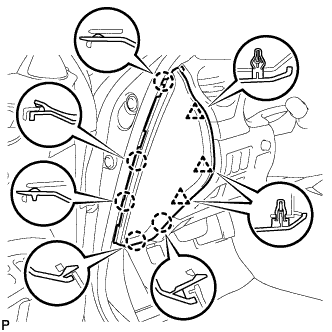 |
| 6. INSTALL FRONT DOOR OPENING TRIM COVER LH (for LHD) |
Engage the 6 claws and install the front door opening trim cover LH.
 |
| 7. INSTALL FRONT DOOR SCUFF PLATE LH (for LHD) |
| 8. INSTALL LOWER INSTRUMENT PANEL FINISH PANEL SUB-ASSEMBLY (for RHD) |
Connect the connectors.
|
Engage the 7 clips and install the lower instrument panel finish panel sub-assembly.
| 9. INSTALL NO. 1 INSTRUMENT PANEL UNDER COVER SUB-ASSEMBLY (for RHD) |
Connect the connectors.
|
Insert the No. 1 instrument panel under cover sub-assembly into the guide as shown in the illustration.
Engage the 2 claws.
Install the No. 1 instrument panel under cover sub-assembly with the 2 screws <E>.