Dtc B2782 Power Source Control Ecu Malfunction
Steering. Lexus Is250, Is220D. Gse20 Ale20
DESCRIPTION
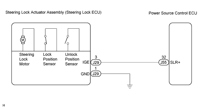
WIRING DIAGRAM
INSPECTION PROCEDURE
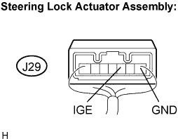
INSPECT STEERING LOCK ACTUATOR ASSEMBLY (STEERING LOCK ECU)
CHECK HARNESS AND CONNECTOR (STEERING LOCK ACTUATOR ASSEMBLY - BODY GROUND)
CHECK HARNESS AND CONNECTOR (STEERING LOCK ACTUATOR ASSEMBLY - POWER SOURCE CONTROL ECU)
DTC B2782 Power Source Control ECU Malfunction |
DESCRIPTION
The power source control ECU controls the power supply to activate the steering lock motor. This prevents the steering from being locked while the vehicle is moving.DTC No.
| DTC Detecting Condition
| Trouble Area
|
B2782
| Steering lock motor drive control circuit is defective.
| - Wire harness
- Steering lock actuator assembly (Steering lock ECU)
- Power source control ECU
|
WIRING DIAGRAM
INSPECTION PROCEDURE
| 1.INSPECT STEERING LOCK ACTUATOR ASSEMBLY (STEERING LOCK ECU) |
Measure the voltage according to the value(s) in the table below.
- Standard voltage:
Tester connection
(Symbols)
| Condition
| Specified condition
|
J29-3 (IGE) - J29-1 (GND)
| Specified condition is checked after performing the following:
- Engine switch off
- Turn the engine switch on (ACC or IG)
| - Motor activated: Below 1 V
- Motor not activated: 10 to 12 V
|
J29-3 (IGE) - J29-1 (GND)
| Specified condition is checked after performing the following:
- Shift the shift lever to the P position
- Turn the engine switch off
- Open the driver's door
| - Motor activated: Below 1 V
- Motor not activated: 10 to 12 V
|
- HINT:
- The steering lock ECU and steering lock actuator assembly are supplied as a unit.
| | REPLACE STEERING LOCK ACTUATOR ASSEMBLY (STEERING LOCK ECU) |
|
|
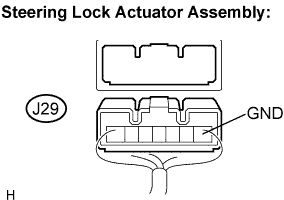
| 2.CHECK HARNESS AND CONNECTOR (STEERING LOCK ACTUATOR ASSEMBLY - BODY GROUND) |
Disconnect the J29 connector from the steering lock actuator assembly.
Measure the resistance according to the value(s) in the table below.
- Standard resistance:
Tester connection
(Symbols)
| Condition
| Specified condition
|
J29-1 (GND) - Body ground
| Always
| Below 1 Ω
|
| | REPAIR OR REPLACE HARNESS OR CONNECTOR |
|
|
| 3.CHECK HARNESS AND CONNECTOR (STEERING LOCK ACTUATOR ASSEMBLY - POWER SOURCE CONTROL ECU) |
Disconnect the J55 connector from the power source control ECU.
Measure the resistance according to the value(s) in the table below.
- Standard resistance:
Tester connection
(Symbols)
| Condition
| Specified condition
|
J29-3 (IGE) - J55-32 (SLR+)
| Always
| Below 1 Ω
|
J29-3 (IGE) - Body ground
| Always
| 10 kΩ or higher
|
| | REPAIR OR REPLACE HARNESS OR CONNECTOR |
|
|
| OK |
|
|
|
| REPLACE POWER SOURCE CONTROL ECU |
|