Vehicle Stability Control System (W/O Vdim) Tc And Cg Terminal Circuit
Brake. Lexus Is250, Is220D. Gse20 Ale20
DESCRIPTION
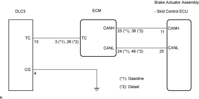
WIRING DIAGRAM
INSPECTION PROCEDURE
CHECK CAN COMMUNICATION SYSTEM
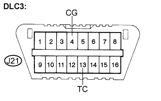
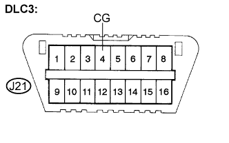
INSPECT DLC3
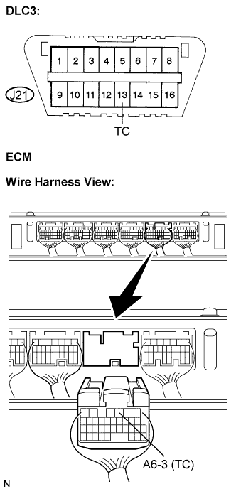
CHECK HARNESS AND CONNECTOR (TC of DLC3 - ECM)
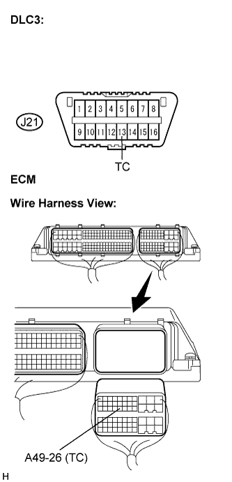
CHECK HARNESS AND CONNECTOR (TC of DLC3 - ECM)
CHECK HARNESS AND CONNECTOR (CG of DLC3 - BODY GROUND)
CHECK ECM (TC of DLC3 INPUT)
VEHICLE STABILITY CONTROL SYSTEM (w/o VDIM) - TC and CG Terminal Circuit |
DESCRIPTION
Connecting terminals TC and CG of the DLC3 causes the ECU to display the DTC by blinking the ABS warning light.
WIRING DIAGRAM
INSPECTION PROCEDURE
- NOTICE:
- When replacing the brake actuator assembly, perform zero point calibration (Click here).
| 1.CHECK CAN COMMUNICATION SYSTEM |
Check if the CAN communication system DTC is output (Click here for LHD (gasoline), Click here for RHD (gasoline), Click here for LHD (diesel), or Click here for RHD (diesel)).
- Result:
Condition
| Proceed to
|
DTC is not output
| A
|
DTC is output
| B
|
| | INSPECT CAN COMMUNICATION SYSTEM |
|
|
Turn the engine switch on (IG).
Measure the voltage according to the value(s) in the table below.
- Standard voltage:
Tester Connection
| Condition
| Specified Condition
|
J21-13 (TC) - J21-4 (CG)
| Engine switch on (IG)
| 10 to 14 V
|
- Result:
Result
| Proceed to
|
NG (for gasoline)
| A
|
NG (for diesel)
| B
|
OK
| C
|
| 3.CHECK HARNESS AND CONNECTOR (TC of DLC3 - ECM) |
Turn the engine switch off.
Disconnect the ECM connector.
Measure the resistance according to the value(s) in the table below.
- Standard resistance:
Tester connection
| Condition
| Specified condition
|
J21-13 (TC) - A6-3 (TC)
| Always
| Below 1 Ω
|
J21-13 (TC) - Body ground
| Always
| 10 kΩ or higher
|
| NG |
|
|
|
| REPAIR OR REPLACE HARNESS OR CONNECTOR |
|
| 4.CHECK HARNESS AND CONNECTOR (TC of DLC3 - ECM) |
Turn the engine switch off.
Disconnect the ECM connector.
Measure the resistance according to the value(s) in the table below.
- Standard resistance:
Tester connection
| Condition
| Specified condition
|
J21-13 (TC) - A49-26 (TC)
| Always
| Below 1 Ω
|
J21-13 (TC) - Body ground
| Always
| 10 kΩ or higher
|
| | REPAIR OR REPLACE HARNESS OR CONNECTOR |
|
|
| 5.CHECK HARNESS AND CONNECTOR (CG of DLC3 - BODY GROUND) |
Measure the resistance according to the value(s) in the table below.
- Standard resistance:
Tester Connection
| Condition
| Specified Condition
|
J21-4 (CG) - Body ground
| Always
| Below 1 Ω
|
| | REPAIR OR REPLACE HARNESS OR CONNECTOR |
|
|
| 6.CHECK ECM (TC of DLC3 INPUT) |
Reconnect the ECM connector.
Using SST, connect terminals TC and CG of the DLC3.
Turn the engine switch on (IG).
Check that the engine warning light is blinking.
- Result:
Condition
| Proceed to
|
Engine warning light is blinking
| A
|
Engine warning light is not blinking
| B
|
- HINT:
- If troubleshooting has been carried out according to the Problem Symptoms Table, refer back to the table and proceed to the next step before replacing the part (Click here).
| | REPAIR OR REPLACE WIRE HARNESS OR ECM (TC of ECM CIRCUIT) |
|
|
| A |
|
|
|
| REPLACE BRAKE ACTUATOR ASSEMBLY |
|