Dtc C0226/21 Sfr Solenoid Circuit
Brake. Lexus Is250, Is220D. Gse20 Ale20
DESCRIPTION
WIRING DIAGRAM
INSPECTION PROCEDURE
INSPECT BRAKE ACTUATOR ASSEMBLY
CHECK HARNESS AND CONNECTOR (SKID CONTROL ECU - BRAKE ACTUATOR ASSEMBLY)
RECONFIRM DTC
DTC C0226/21 SFR Solenoid Circuit |
DTC C0236/22 SFL Solenoid Circuit |
DTC C0246/23 SRR Solenoid Circuit |
DTC C0256/24 SRL Solenoid Circuit |
DESCRIPTION
These solenoids turn on when signals are received from the skid control ECU and control the pressure acting on the wheel cylinders to control the braking force.DTC No.
| DTC Detection Condition
| Trouble Area
|
C0226/21
C0236/22
C0246/23
C0256/24
| When any of the following is detected:
- Open or short in the solenoid circuit continues for 0.05 seconds or more.
- While solenoid OFF is being output, an open circuit continues for 0.05 seconds or more.
- While solenoid ON is being output, overcurrent continues for 0.05 seconds or more.
- While solenoid ON is being output, an open circuit continues for 0.1 seconds or more.
- While solenoid OFF is being output, current continues to be applied for 0.1 seconds or more.
- Short to GND in the solenoid continues for 0.1 seconds or more.
| - Solenoid circuit
- Skid control ECU
|
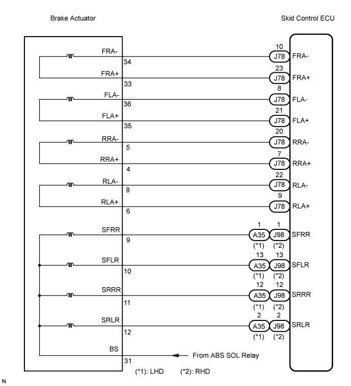
WIRING DIAGRAM
INSPECTION PROCEDURE
- NOTICE:
- When replacing the skid control ECU, perform zero point calibration and store system information (Click here ).
- HINT:
- When C0278/11 or C0279/12 is output together with C0226/21, C0236/22, C0246/23, or C0256/24, inspect and repair the trouble areas indicated by C0278/11 or C0279/12 first.
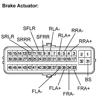
| 1.INSPECT BRAKE ACTUATOR ASSEMBLY |
Disconnect the brake actuator connector.
Measure the resistance according to the value(s) in the table below.
- Standard resistance:
Tester Connection
| Condition
| Specified Condition
|
31 (BS) - 9 (SFRR)
| Always
| 4.0 to 4.6 Ω
at 25°C (77°F)
|
9 (SFRR) - Body ground
| Always
| 10 kΩ or higher
|
31 (BS) - 10 (SFLR)
| Always
| 4.0 to 4.6 Ω
at 25°C (77°F)
|
10 (SFLR) - Body ground
| Always
| 10 kΩ or higher
|
31 (BS) - 11 (SRRR)
| Always
| 4.0 to 4.6 Ω
at 25°C (77°F)
|
11 (SRRR) - Body ground
| Always
| 10 kΩ or higher
|
31 (BS) - 12 (SRLR)
| Always
| 4.0 to 4.6 Ω
at 25°C (77°F)
|
12 (SRLR) - Body ground
| Always
| 10 kΩ or higher
|
33 (FRA+) - 34 (FRA-)
| Always
| 4.8 to 5.4 Ω
at 25°C (77°F)
|
34 (FRA-) - Body ground
| Always
| 10 kΩ or higher
|
35 (FLA+) - 36 (FLA-)
| Always
| 4.8 to 5.4 Ω
at 25°C (77°F)
|
36 (FLA-) - Body ground
| Always
| 10 kΩ or higher
|
4 (RRA+) - 5 (RRA-)
| Always
| 4.8 to 5.4 Ω
at 25°C (77°F)
|
5 (RRA-) - Body ground
| Always
| 10 kΩ or higher
|
6 (RLA+) - 8 (RLA-)
| Always
| 4.8 to 5.4 Ω
at 25°C (77°F)
|
8 (RLA-) - Body ground
| Always
| 10 kΩ or higher
|
| | REPLACE BRAKE ACTUATOR ASSEMBLY |
|
|
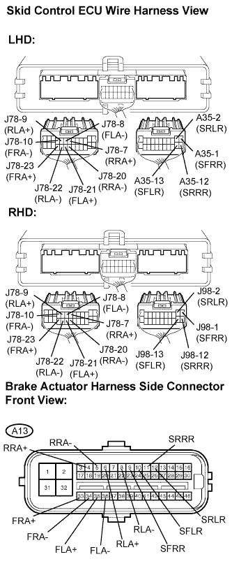
| 2.CHECK HARNESS AND CONNECTOR (SKID CONTROL ECU - BRAKE ACTUATOR ASSEMBLY) |
Disconnect the skid control ECU connector.
Measure the resistance according to the value(s) in the table below.
- Standard resistance:
- LHD:
Tester Connection
| Condition
| Specified Condition
|
A35-1 (SFRR) - A13-9 (SFRR)
| Always
| Below 1 Ω
|
A35-1 (SFRR) - Body ground
| Always
| 10 kΩ or higher
|
A35-13 (SFLR) - A13-10 (SFLR)
| Always
| Below 1 Ω
|
A35-13 (SFLR) - Body ground
| Always
| 10 kΩ or higher
|
A35-12 (SRRR) - A13-11 (SRRR)
| Always
| Below 1 Ω
|
A35-12 (SRRR) - Body ground
| Always
| 10 kΩ or higher
|
A35-2 (SRLR) - A13-12 (SRLR)
| Always
| Below 1 Ω
|
A35-2 (SRLR) - Body ground
| Always
| 10 kΩ or higher
|
J78-23 (FRA+) - A13-33 (FRA+)
| Always
| Below 1 Ω
|
J78-23 (FRA+) - Body ground
| Always
| 10 kΩ or higher
|
J78-10 (FRA-) - A13-34 (FRA-)
| Always
| Below 1 Ω
|
J78-10 (FRA-) - Body ground
| Always
| 10 kΩ or higher
|
J78-21 (FLA+) - A13-35 (FLA+)
| Always
| Below 1 Ω
|
J78-21 (FLA+) - Body ground
| Always
| 10 kΩ or higher
|
J78-8 (FLA-) - A13-36 (FLA-)
| Always
| Below 1 Ω
|
J78-8 (FLA-) - Body ground
| Always
| 10 kΩ or higher
|
J78-7 (RRA+) - A13-4 (RRA+)
| Always
| Below 1 Ω
|
J78-7 (RRA+) - Body ground
| Always
| 10 kΩ or higher
|
J78-20 (RRA-) - A13-5 (RRA-)
| Always
| Below 1 Ω
|
J78-20 (RRA-) - Body ground
| Always
| 10 kΩ or higher
|
J78-9 (RLA+) - A13-6 (RLA+)
| Always
| Below 1 Ω
|
J78-9 (RLA+) - Body ground
| Always
| 10 kΩ or higher
|
J78-22 (RLA-) - A13-8 (RLA-)
| Always
| Below 1 Ω
|
J78-22 (RLA-) - Body ground
| Always
| 10 kΩ or higher
|
- RHD:
Tester Connection
| Condition
| Specified Condition
|
J98-1 (SFRR) - A13-9 (SFRR)
| Always
| Below 1 Ω
|
J98-1 (SFRR) - Body ground
| Always
| 10 kΩ or higher
|
J98-13 (SFLR) - A13-10 (SFLR)
| Always
| Below 1 Ω
|
J98-13 (SFLR) - Body ground
| Always
| 10 kΩ or higher
|
J98-12 (SRRR) - A13-11 (SRRR)
| Always
| Below 1 Ω
|
J98-12 (SRRR) - Body ground
| Always
| 10 kΩ or higher
|
J98-2 (SRLR) - A13-12 (SRLR)
| Always
| Below 1 Ω
|
J98-2 (SRLR) - Body ground
| Always
| 10 kΩ or higher
|
J78-23 (FRA+) - A13-33 (FRA+)
| Always
| Below 1 Ω
|
J78-23 (FRA+) - Body ground
| Always
| 10 kΩ or higher
|
J78-10 (FRA-) - A13-34 (FRA-)
| Always
| Below 1 Ω
|
J78-10 (FRA-) - Body ground
| Always
| 10 kΩ or higher
|
J78-21 (FLA+) - A13-35 (FLA+)
| Always
| Below 1 Ω
|
J78-21 (FLA+) - Body ground
| Always
| 10 kΩ or higher
|
J78-8 (FLA-) - A13-36 (FLA-)
| Always
| Below 1 Ω
|
J78-8 (FLA-) - Body ground
| Always
| 10 kΩ or higher
|
J78-7 (RRA+) - A13-4 (RRA+)
| Always
| Below 1 Ω
|
J78-7 (RRA+) - Body ground
| Always
| 10 kΩ or higher
|
J78-20 (RRA-) - A13-5 (RRA-)
| Always
| Below 1 Ω
|
J78-20 (RRA-) - Body ground
| Always
| 10 kΩ or higher
|
J78-9 (RLA+) - A13-6 (RLA+)
| Always
| Below 1 Ω
|
J78-9 (RLA+) - Body ground
| Always
| 10 kΩ or higher
|
J78-22 (RLA-) - A13-8 (RLA-)
| Always
| Below 1 Ω
|
J78-22 (RLA-) - Body ground
| Always
| 10 kΩ or higher
|
| | REPAIR OR REPLACE HARNESS OR CONNECTOR |
|
|
Reconnect the skid control ECU connector and the brake actuator connector.
Clear the DTC (Click here).
Start the engine.
Check if the same DTC is recorded (Click here).
- Result:
Condition
| Proceed to
|
DTCs (C0226/21, C0236/22, C0246/23, and/or C0256/24) are not output
| A
|
DTCs (C0226/21, C0236/22, C0246/23, and/or C0256/24) are output
| B
|
- HINT:
- If the normal system code is output (the trouble code is not output), slightly jiggle the connectors, wire harness, and fuses of the skid control ECU and brake actuator assembly. Make sure that no DTCs are output.
- If any DTCs are output while jiggling a connector or wire harness of the skid control ECU and brake actuator assembly, inspect and repair the connector or wire harness.
| A |
|
|
|
| USE SIMULATION METHOD TO CHECK |
|