Rear Differential Carrier (For 2Ad-Fhv) Reassembly
INSTALL DIFFERENTIAL RING GEAR
INSTALL REAR DIFFERENTIAL CASE BEARING
INSTALL REAR DRIVE PINION REAR TAPERED ROLLER BEARING
INSTALL REAR DRIVE PINION FRONT TAPERED ROLLER BEARING
INSTALL REAR DIFFERENTIAL DUST DEFLECTOR
INSTALL DIFFERENTIAL DRIVE PINION
INSTALL REAR DIFFERENTIAL DRIVE PINION OIL SLINGER
ADJUST DIFFERENTIAL DRIVE PINION PRELOAD
INSTALL REAR DIFFERENTIAL CASE SUB-ASSEMBLY
INSTALL REAR DIFFERENTIAL CASE BEARING
INSTALL REAR DIFFERENTIAL SIDE GEAR SHAFT SNAP RING
ADJUST DIFFERENTIAL SIDE BEARING PRELOAD
ADJUST TOTAL PRELOAD
INSPECT TOOTH CONTACT BETWEEN RING GEAR AND DRIVE PINION
REMOVE REAR DIFFERENTIAL SIDE GEAR SHAFT SNAP RING
REMOVE REAR DIFFERENTIAL SIDE GEAR SHAFT SNAP RING
REMOVE REAR DIFFERENTIAL CASE BEARING
REMOVE REAR DIFFERENTIAL CASE BEARING
REMOVE REAR DIFFERENTIAL CASE SUB-ASSEMBLY
REMOVE REAR DRIVE PINION NUT
REMOVE REAR DRIVE PINION COMPANION FLANGE
REMOVE REAR DIFFERENTIAL DRIVE PINION OIL SLINGER
REMOVE DIFFERENTIAL DRIVE PINION
REMOVE REAR DRIVE PINION FRONT TAPERED ROLLER BEARING
INSTALL REAR DIFFERENTIAL DRIVE PINION BEARING SPACER
INSTALL DIFFERENTIAL DRIVE PINION
INSTALL REAR DIFFERENTIAL DRIVE PINION OIL SLINGER
INSTALL REAR DIFFERENTIAL CARRIER OIL SEAL
INSTALL REAR DRIVE PINION COMPANION FLANGE
INSTALL REAR DIFFERENTIAL CASE SUB-ASSEMBLY
INSTALL REAR DIFFERENTIAL CASE BEARING
INSTALL REAR DIFFERENTIAL SIDE GEAR SHAFT SNAP RING
ADJUST DIFFERENTIAL DRIVE PINION PRELOAD
INSPECT TOTAL PRELOAD
INSPECT DIFFERENTIAL RING GEAR BACKLASH
INSPECT RUNOUT OF DIFFERENTIAL DRIVE PINION
INSTALL REAR DRIVE PINION NUT
INSTALL REAR DIFFERENTIAL SIDE GEAR SHAFT OIL SEAL
INSTALL REAR DIFFERENTIAL DRAIN PLUG
REMOVE REAR DIFFERENTIAL CARRIER
INSTALL REAR DIFFERENTIAL BREATHER PLUG OIL DEFLECTOR
INSTALL REAR DIFFERENTIAL CARRIER COVER
INSTALL REAR DIFFERENTIAL CARRIER COVER BREATHER PLUG
Rear Differential Carrier (For 2Ad-Fhv) -- Reassembly |
| 1. INSTALL DIFFERENTIAL RING GEAR |
Clean the contact surfaces of the differential case and ring gear.
Clean the differential ring gear set bolt hole.
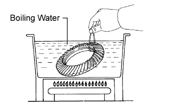
Heat the ring gear to approximately 100°C (212°F) in boiling water.
- CAUTION:
- Use thick gloves to protect your hands because the ring gear is hot.
Carefully take the ring gear out of the boiling water.
Hold the differential case in a vise between aluminum plates.
- NOTICE:
- Do not overtighten the vise.
After the moisture on the ring gear has completely evaporated, quickly install the ring gear to the differential case.
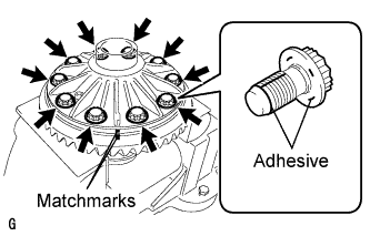
Align the matchmarks on the ring gear and the differential case.
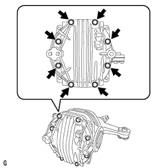
After the ring gear has cooled sufficiently, install 10 new ring gear set bolts to which adhesive has been applied.
- Adhesive:
- Toyota Genuine Adhesive TB1360K, Three Bond TB1360K or equivalent.
- NOTICE:
- New ring gear set bolts should be used every time the ring gear is installed.
Tighten the 10 set bolts uniformly, a little at a time.
- Torque:
- 64 N*m{650 kgf*cm, 47 ft.*lbf}
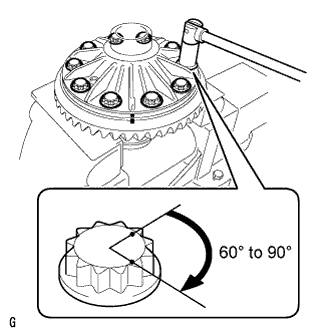
Tighten the bolts further by 60° to 90°.
- NOTICE:
- Tighten the bolts in a diagonal pattern.
| 2. INSTALL REAR DIFFERENTIAL CASE BEARING |
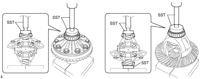
Using SST and a press, install the case bearing inner races LH and RH to the differential case.
- SST
- 09950-60010(09951-00560,09951-00570)
09950-70010(09951-07100)
- NOTICE:
- Do not apply hypoid gear oil to a new bearing.
- Do not deform the bearing cage. Set the SST to the center of the differential case.
- If the bearing is replaced, replace the bearing and its outer race as a set.
- The bearings for the two different sides of the differential case have different part numbers. Install 90366-50087 to the differential case on the ring gear tooth side, and install 90366-50027 to the differential case on the side that does not have the ring gear teeth. Use the part numbers to determine correct bearing placement.
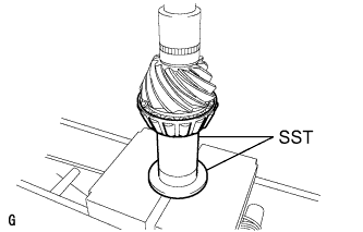
| 3. INSTALL REAR DRIVE PINION REAR TAPERED ROLLER BEARING |
Using SST and a press, install the rear drive pinion rear tapered roller bearing inner race to the drive pinion.
- SST
- 09316-60011(09316-00031)
09612-10093(09613-22011)
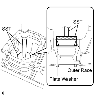
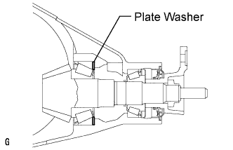
Using SST and a press, install the rear drive pinion rear tapered roller bearing outer race and plate washer.
- SST
- 09255-10012
09950-70010(09951-07200)
- HINT:
- Select a plate washer of the same thickness as the removed one.
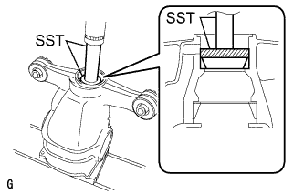
| 4. INSTALL REAR DRIVE PINION FRONT TAPERED ROLLER BEARING |
Using SST and a press, install the rear drive pinion front tapered roller bearing outer race.
- SST
- 09950-60020(09951-00710)
09950-70010(09951-07100)
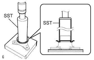
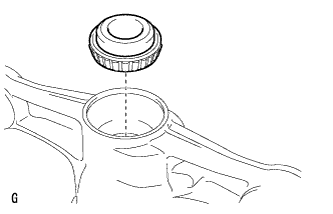
| 5. INSTALL REAR DIFFERENTIAL DUST DEFLECTOR |
- HINT:
- Perform this procedure only when replacing the dust deflector.
Using SST and a press, insert a new dust deflector into the companion flange.
- SST
- 09316-60011(09316-00011)
- NOTICE:
- Slowly press in the dust deflector and do not press it excessively.
- If any burrs remain after pressing in the deflector, remove them.
| 6. INSTALL DIFFERENTIAL DRIVE PINION |
Using SST and a press, install the differential drive pinion.
- SST
- 09316-60011(09316-00011)
09608-04031
- HINT:
- Install the spacer and oil seal after adjusting the tooth contact pattern.
| 7. INSTALL REAR DIFFERENTIAL DRIVE PINION OIL SLINGER |
Install the drive pinion oil slinger.
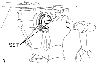
| 8. ADJUST DIFFERENTIAL DRIVE PINION PRELOAD |
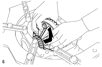
Using SST, install the companion flange.
- SST
- 09950-30012(09951-03010,09954-03010,09956-03060,09955-03040)
- NOTICE:
- Install the companion flange so that there is a slight looseness on the drive pinion because the bearing spacer is not yet installed.
- Apply grease to the threads and tip of the SST center bolt before use.
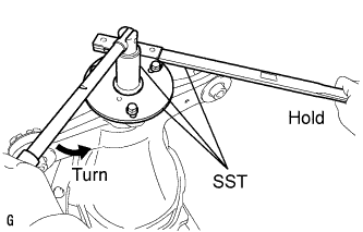
Coat the threads of the drive pinion nut with hypoid gear oil LSD.
Using SST to hold the flange, tighten the drive pinion nut.
- SST
- 09229-55010
09330-00021
- HINT:
- Tighten the nut to approximately 100 N*m (1,020 kgf*cm, 74 ft.*lbf), and tighten it further while checking the preload.
- NOTICE:
- Apply hypoid gear oil LSD to the nut and the threads of the drive pinion.
- As there is no bearing spacer, tighten the nut a little at a time and do not overtighten it.
Turn the bearing clockwise and counterclockwise several times to stabilize it.
- SST
- 09229-55010
Using SST and a torque wrench, measure the preload.
- Drive pinion preload (at starting):
Specifications
| Preload
|
New bearing
| 1.12 to 1.70 N*m (11.4 to 17.3 kgf*cm, 9.9 to 15.0 in.*lbf)
|
Reused bearing
| 0.40 to 0.70 N*m (4.1 to 7.2 kgf*cm, 3.5 to 6.2 in.*lbf)
|
- NOTICE:
- Record the preload for total preload measurement.
If the preload is not within the specified range, adjust the rear differential drive pinion preload or repair as necessary.
| 9. INSTALL REAR DIFFERENTIAL CASE SUB-ASSEMBLY |
Insert the differential case from the ring gear tooth side to install the differential case.
- NOTICE:
- Do not damage the case bearing and ring gear.
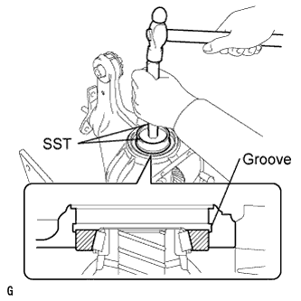
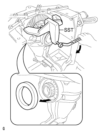
| 10. INSTALL REAR DIFFERENTIAL CASE BEARING |
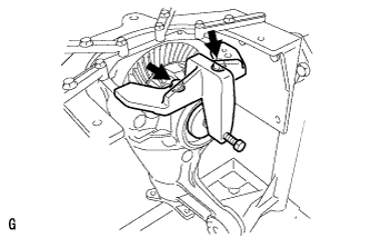
Using SST and a hammer, install the ring gear tooth side case bearing outer race.
- SST
- 09608-32010
09950-70010(09951-07200)
- HINT:
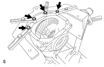
- Tap in the case bearing outer race until half of the side gear shaft snap ring groove of the differential carrier can be seen.
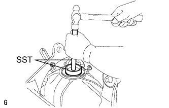
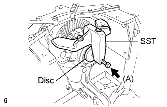
Install SST to the differential carrier.
- SST
- 09571-50010
Tighten the SST bolt until the SST disc slightly touches the case bearing outer race.
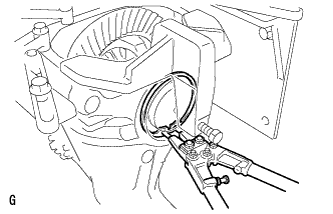
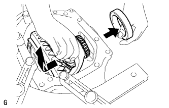
Using SST and a hammer, install the ring gear back surface side case bearing outer race.
- SST
- 09608-32010
09950-70010(09951-07200)
- HINT:
- Tap in the case bearing outer race until it touches the case bearing inner race roller.
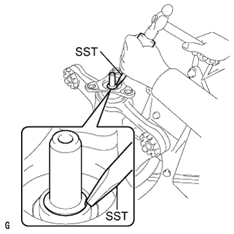
| 11. INSTALL REAR DIFFERENTIAL SIDE GEAR SHAFT SNAP RING |
Using snap ring pliers, install the thinnest side gear shaft snap ring on the back surface of the ring gear.
- HINT:
- If the final gear set (drive pinion and ring gear) and case bearing are new, select a thinner side gear shaft snap ring and install it.
- If the final gear set (drive pinion and ring gear) and case bearing are reused, install a side gear shaft snap ring with the same thickness as the removed one.
Install a dial indicator to the differential carrier.
Tighten the SST bolt. Push in the differential case bearing (outer race) until an approximately 0.1 mm (0.004 in.) clearance is created between the bearing (outer race) and the differential side gear shaft snap ring.
- SST
- 09571-50010
- NOTICE:
- Observe the dial indicator and ensure that the bearing (outer race) is not pushed in more than 0.2 mm (0.008 in.).
- HINT:
- Install the dial indicator to the position as close to the differential carrier cover side (upper side in the illustration) of the bearing (outer race) as possible.
- Tighten the SST bolt to apply the preload to the case bearing.
Turn the ring gear clockwise and counterclockwise several times.
Using a dial indicator, measure the backlash of the ring gear in 3 positions.
- Backlash:
- 0.08 to 0.13 mm (0.0031 to 0.0051 in.)
- NOTICE:
- The difference between the maximum and minimum values must be within 0.05 mm (0.002 in.).
- HINT:
- Record the measured backlash to use as a reference for selecting a side gear shaft snap ring.
- If the backlash is not within the specified range, replace the rear differential side gear shaft snap ring on the ring gear tooth side with a snap ring of a different thickness as described in the below procedure.
- Inspect tooth contact to use the result as a reference for selecting a side gear shaft snap ring.
Loosen the SST bolt and separate the SST disc from the case bearing outer race on the ring gear tooth side.
Using SST and a hammer, create a clearance between the side gear shaft snap ring on the ring gear back surface side and case bearing outer race.
- SST
- 09608-32010
09950-70010(09951-07200)
Using snap ring pliers, remove the side gear shaft snap ring on the ring gear back surface side.
Using snap ring pliers, install a side gear shaft snap ring with different thickness.
- HINT:
- When the side gear shaft snap ring thickness changes by 0.02 mm (0.0008 in.), the backlash also changes by 0.02 mm (0.0008 in.).
Snap ring thicknessThickness mm (in.)
| Thickness mm (in.)
| Thickness mm (in.)
|
3.66 (0.1441)
| 3.92 (0.1543)
| 4.18 (0.1646)
|
3.68 (0.1449)
| 3.94 (0.1551)
| 4.20 (0.1654)
|
3.70 (0.1457)
| 3.96 (0.1559)
| 4.22 (0.1661)
|
3.72 (0.1465)
| 3.98 (0.1567)
| 4.24 (0.1669)
|
3.74 (0.1472)
| 4.00 (0.1575)
| 4.26 (0.1677)
|
3.76 (0.1480)
| 4.02 (0.1583)
| 4.28 (0.1685)
|
3.78 (0.1488)
| 4.04 (0.1591)
| 4.30 (0.1693)
|
3.80 (0.1496)
| 4.06 (0.1598)
| 4.32 (0.1701)
|
3.82 (0.1503)
| 4.08 (0.1606)
| 4.34 (0.1709)
|
3.84 (0.1512)
| 4.10 (0.1614)
| 4.36 (0.1717)
|
3.86 (0.1520)
| 4.12 (0.1622)
| 4.38 (0.1724)
|
3.88 (0.1528)
| 4.14 (0.1630)
| 4.40 (0.1732)
|
3.90 (0.1535)
| 4.16 (0.1638)
| 4.42 (0.1740)
|
Using a plastic hammer, lightly tap the ring gear tooth side of the differential carrier.
Install a dial indicator to the differential carrier.
Tighten the SST bolt. Push in the differential case bearing (outer race) until an approximately 0.1 mm (0.004 in.) clearance is created between the bearing (outer race) and the differential side gear shaft snap ring.
- SST
- 09571-50010
- NOTICE:
- Observe the dial indicator and ensure that the bearing (outer race) is not pushed in more than 0.2 mm (0.008 in.).
- HINT:
- Install the dial indicator to the position as close to the differential carrier cover side (upper side in the illustration) of the bearing (outer race) as possible.
Using a dial indicator, measure the backlash of the ring gear in 3 positions.
- Backlash:
- 0.08 to 0.13 mm (0.0031 to 0.0051 in.)
If the backlash is not within the specified range, replace the side gear shaft snap ring on the back surface of the ring gear with a snap ring of a different thickness.
- HINT:
- Record the measured backlash to use as a reference for selecting a side gear shaft snap ring.
- Inspect tooth contact to use the result as a reference for selecting a side gear shaft snap ring.
| 12. ADJUST DIFFERENTIAL SIDE BEARING PRELOAD |
Install a dial indicator to the differential carrier.
Tighten the SST bolt. Push in the differential case bearing (outer race) until an approximately 0.1 mm (0.004 in.) clearance is created between the bearing (outer race) and the differential side gear shaft snap ring.
- SST
- 09571-50010
- NOTICE:
- Observe the dial indicator and ensure that the bearing (outer race) is not pushed in more than 0.2 mm (0.008 in.).
- HINT:
- Install the dial indicator to the position as close to the differential carrier cover side (upper side in the illustration) of the bearing (outer race) as possible.
Using snap ring pliers, install the thinnest side gear shaft snap ring on the ring gear tooth side.
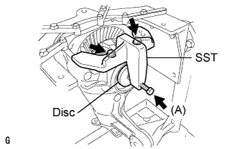
Remove the dial indicator and loosen the bolt (A) until the SST disc is separated from the case bearing outer race.
Using a plastic hammer, lightly tap the ring gear tooth side of the differential carrier.
Using a dial indicator, measure the backlash of the ring gear in 3 positions. If even one backlash reading is smaller than the specified value, adjust the differential ring gear backlash by replacing the side gear shaft snap ring on the ring gear tooth side with a thicker one.
- Backlash:
- 0.08 to 0.13 mm (0.0031 to 0.0051 in.)
- HINT:
- If a value is not within the specified range, replace it with a snap ring of different thickness in the following procedure.
Loosen the SST bolt and separate the SST disc from the case bearing outer race on the ring gear tooth side.
|
Using SST and a torque wrench, measure the preload with the teeth of the drive pinion and ring gear in contact.
- SST
- 09229-55010
- Total preload (at starting):
Grade: luxurySpecifications
| Preload
|
New bearing
| 1.82 to 3.79 N*m (18.6 to 38.6 kgf*cm, 16.1 to 33.5 in.*lbf)
|
Reused bearing
| 1.10 to 2.79 N*m (11.2 to 28.5 kgf*cm, 9.7 to 24.7 in.*lbf)
|
Grade: sportSpecifications
| Preload
|
New bearing
| 1.65 to 3.28 N*m (16.8 to 33.4 kgf*cm, 14.6 to 29.0 in.*lbf)
|
Reused bearing
| 0.93 to 2.28 N*m (9.5 to 23.2 kgf*cm, 8.2 to 20.2 in.*lbf)
|
- NOTICE:
- If the measured preload is less than the specified value, replace the rear differential side gear shaft snap ring of the ring gear tooth surface side with a thicker one.
- If the preload is greater than the specified value, replace the rear differential side gear shaft snap ring of the ring gear tooth surface side with a thinner one.
- HINT:
- When the rear differential side gear shaft snap ring thickness changes by 0.02 mm (0.0008 in.), the total preload will change by approximately 0.1 N*m (1 kgf*cm, 0.9 in.*lbf).
Set a dial indicator to the end of the differential ring gear face.
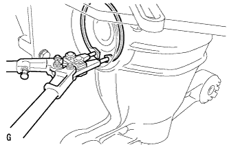
While holding the rear drive pinion companion flange rear, rotate the ring gear and measure the backlash.
- Backlash:
- 0.08 to 0.13 mm (0.0031 to 0.0051 in.)
- NOTICE:
- If the measured value is not within the specified range, adjust it by increasing or decreasing the thickness of both right and left side gear shaft snap rings equally.
- When the side gear shaft snap ring thickness changes by 0.02 mm (0.0008 in.), the backlash will also change by approximately 0.02 mm (0.0008 in.).
Recheck the total preload.
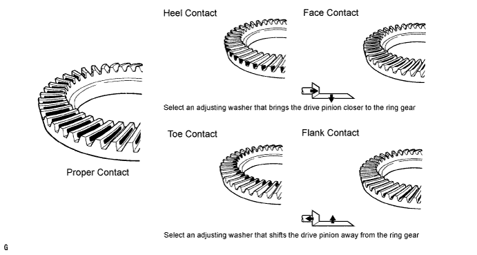
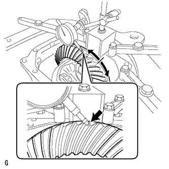
| 14. INSPECT TOOTH CONTACT BETWEEN RING GEAR AND DRIVE PINION |
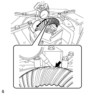
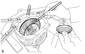
Coat 3 or 4 teeth at the 3 different positions on the ring gear with Prussian blue.
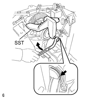
Rotate the ring gear in both directions.
Inspect the tooth contact pattern.
|
If the teeth are not contacting properly, use the following table to select a proper plate washer for correction.
- HINT:
- If the contact pattern is face contact or flank contact, tooth contact may be adjustable while keeping the backlash within the specified range.
- If the thickness of the drive pinion washer has been changed, adjust the backlash and measure the total preload.
Washer thicknessThickness mm (in.)
| No.
| Thickness mm (in.)
| No.
| Thickness mm (in.)
| No.
|
1.87 (0.0736)
| 87
| 2.01 (0.0791)
| 01
| 2.15 (0.0846)
| 15
|
1.88 (0.0740)
| 88
| 2.02 (0.0795)
| 02
| 2.16 (0.0850)
| 16
|
1.89 (0.0744)
| 89
| 2.03 (0.0799)
| 03
| 2.17 (0.0854)
| 17
|
1.90 (0.0748)
| 90
| 2.04 (0.0803)
| 04
| 2.18 (0.0858)
| 18
|
1.91 (0.0752)
| 91
| 2.05 (0.0807)
| 05
| 2.19 (0.0862)
| 19
|
1.92 (0.0756)
| 92
| 2.06 (0.0811)
| 06
| 2.20 (0.0866)
| 20
|
1.93 (0.0760)
| 93
| 2.07 (0.0815)
| 07
| 2.21 (0.0870)
| 21
|
1.94 (0.0764)
| 94
| 2.08 (0.0819)
| 08
| 2.22 (0.0874)
| 22
|
1.95 (0.0768)
| 95
| 2.09 (0.0823)
| 09
| 2.23 (0.0878)
| 23
|
1.96 (0.0772)
| 96
| 2.10 (0.0827)
| 10
| 2.24 (0.0882)
| 24
|
1.97 (0.0776)
| 97
| 2.11 (0.0831)
| 11
| 2.25 (0.0886)
| 25
|
1.98 (0.0780)
| 98
| 2.12 (0.0835)
| 12
| 2.26 (0.0890)
| 26
|
1.99 (0.0783)
| 99
| 2.13 (0.0839)
| 13
| 2.27 (0.0894)
| 27
|
2.00 (0.0787)
| 00
| 2.14 (0.0843)
| 14
| 2.28 (0.0898)
| 28
|
| 15. REMOVE REAR DIFFERENTIAL SIDE GEAR SHAFT SNAP RING |
Install the SST to the rear differential carrier.
- SST
- 09571-50010
Install a dial indicator to the rear differential carrier.
Tighten the SST bolt. Push in the differential case bearing (outer race) until an approximately 0.1 mm (0.004 in.) clearance is created between the bearing (outer race) and the differential side gear shaft snap ring.
- NOTICE:
- Observe the dial indicator and ensure that the bearing (outer race) is not pushed in more than 0.2 mm (0.008 in.).
- HINT:
- Install the dial indicator to the position as close to the differential carrier cover side (upper side in the illustration) of the bearing (outer race) as possible.
- Approximately 0.1 mm (0.004 in.) clearance between the case bearing outer race and the side gear shaft snap ring is sufficient for the washer to move slightly.
Using snap ring pliers, remove the side gear shaft snap ring on the ring gear tooth side.
Remove the dial indicator and loosen the SST bolt.
- NOTICE:
- Do not remove the SST.
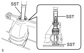
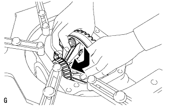
| 16. REMOVE REAR DIFFERENTIAL SIDE GEAR SHAFT SNAP RING |
Using SST and a hammer, create a clearance between the case bearing outer race on the ring gear and side gear shaft snap ring.
- SST
- 09608-32010
09950-70010(09951-07200)
- HINT:
- The clearance is not visible, but tapping the SST with a hammer 3 or 4 times should create sufficient clearance.
Using snap ring pliers, remove the side gear shaft snap ring on the ring gear back surface side.
| 17. REMOVE REAR DIFFERENTIAL CASE BEARING |
Tighten the SST bolt and push out the case bearing outer race on the ring gear back surface side.
- SST
- 09571-50010
- NOTICE:
- Do not drop the case bearing outer race.
- HINT:
- To use as a reference for installation, clearly write the installation positions of the rear differential case bearing (outer race) and the rear differential side gear shaft snap ring.
- Put identification marks on the case bearing outer race to show the location for installation (back side or tooth side), or keep them separate so that they can be distinguished.
Remove the SST.
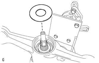
| 18. REMOVE REAR DIFFERENTIAL CASE BEARING |
Raise the ring gear side of the differential case slightly to remove the ring gear tooth side case bearing outer race.
- HINT:
- For reassembly, check the installation position of the case bearing outer race and the side gear shaft snap ring before removing the case bearing outer race. Write down the result.
- Put identification marks on the case bearing outer race to show the location for installation (back side or tooth side), or keep them separate so that they can be distinguished.
| 19. REMOVE REAR DIFFERENTIAL CASE SUB-ASSEMBLY |
Remove the rear differential case assembly.
- NOTICE:
- Do not damage the case bearing.
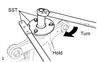
| 20. REMOVE REAR DRIVE PINION NUT |
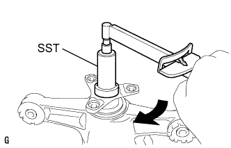
Using SST to hold the flange, remove the drive pinion nut.
- SST
- 09229-55010
09330-00021
09950-30012(09955-03040)
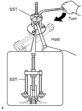
| 21. REMOVE REAR DRIVE PINION COMPANION FLANGE |
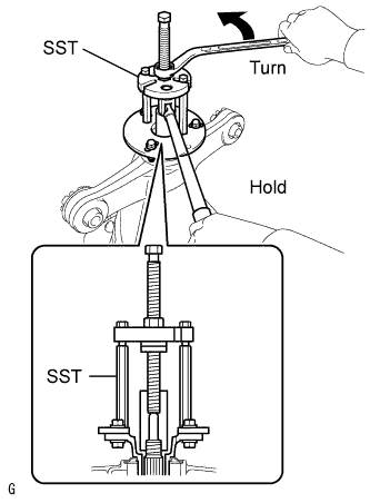
Using SST, remove the companion flange.
- SST
- 09950-30012(09951-03010,09953-03010,09954-03010,09955-03040,09956-03060)
- NOTICE:
- Apply grease to the threads and tip of the SST center bolt before use.
| 22. REMOVE REAR DIFFERENTIAL DRIVE PINION OIL SLINGER |
Remove the differential drive pinion oil slinger.
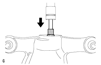
| 23. REMOVE DIFFERENTIAL DRIVE PINION |
Using a press, remove the drive pinion from the differential carrier.
- NOTICE:
- Do not drop the drive pinion.
| 24. REMOVE REAR DRIVE PINION FRONT TAPERED ROLLER BEARING |
Remove the rear drive pinion front tapered roller bearing from the differential carrier.
| 25. INSTALL REAR DIFFERENTIAL DRIVE PINION BEARING SPACER |
Install a new drive pinion bearing spacer to the drive pinion.
- HINT:
- The bearing spacer can be installed in either direction.
| 26. INSTALL DIFFERENTIAL DRIVE PINION |
Using SST and a press, install the differential drive pinion to the differential carrier.
- SST
- 09316-60011(09316-00011,09316-00041)
09608-04031
| 27. INSTALL REAR DIFFERENTIAL DRIVE PINION OIL SLINGER |
Install the differential drive pinion oil slinger to the differential drive pinion.
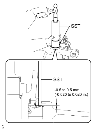
| 28. INSTALL REAR DIFFERENTIAL CARRIER OIL SEAL |
Using SST and a hammer, install a new oil seal.
- SST
- 09316-60011(09316-00011)
09710-30012(09710-04101)
- Oil seal installation depth:
- -0.5 to 0.5 mm (-0.020 to 0.020 in.)
Apply MP grease to the oil seal lip.
| 29. INSTALL REAR DRIVE PINION COMPANION FLANGE |
Using SST, install the companion flange to the drive pinion.
- SST
- 09950-30012(09951-03010,09953-03010,09954-03010,09956-03060,09955-03040)
- NOTICE:
- Apply grease to the threads and tip of the SST center bolt before use.
Coat the threads of a new drive pinion nut with hypoid gear oil LSD.
Use SST to hold the flange and tighten the drive pinion nut.
- SST
- 09229-55010
09330-00021
09950-30012(09955-03040)
- Torque:
- 490 N*m (5,000 kgf*cm, 361 ft.*lbf) or less
- NOTICE:
- Do not tighten excessively, otherwise the threads will be stripped.
- Apply hypoid gear oil LSD to the threads of the nut and drive pinion.
- HINT:
- Tighten the nut to approximately 100 N*m (1,020 kgf*cm, 74 ft.*lbf), then tighten it further while observing the preload.
| 30. INSTALL REAR DIFFERENTIAL CASE SUB-ASSEMBLY |
Insert the differential case from the ring gear tooth side.
- NOTICE:
- Do not damage the case bearing inner race or ring gear.
| 31. INSTALL REAR DIFFERENTIAL CASE BEARING |
Using SST and a hammer, install the ring gear tooth side case bearing outer race.
- SST
- 09608-32010
09950-70010(09951-07200)
- HINT:
- Tap in the case bearing outer race until half of the side gear shaft snap ring groove of the differential carrier can be seen.
Install SST to the differential carrier.
- SST
- 09571-50010
Tighten the SST bolt until the SST disc slightly touches the case bearing outer race.
Using SST and a hammer, install the ring gear back surface side case bearing outer race.
- SST
- 09608-32010
09950-70010(09951-07200)
- HINT:
- Tap in the case bearing outer race until it touches the case bearing inner race roller.
| 32. INSTALL REAR DIFFERENTIAL SIDE GEAR SHAFT SNAP RING |
Using snap ring pliers, install the side gear shaft snap ring in the differential carrier on the ring gear back surface side.
- HINT:
- Use the side gear shaft snap ring installed when performing tooth contact adjustment.
Set a dial indicator on the differential carrier.
Tighten the SST bolt. Push in the differential case bearing (outer race) until an approximately 0.1 mm (0.004 in.) clearance is created between the bearing (outer race) and the differential side gear shaft snap ring.
- NOTICE:
- Observe the dial indicator and ensure that the bearing (outer race) is not pushed in more than 0.2 mm (0.008 in.).
- HINT:
- Install the dial indicator to the position as close to the differential carrier cover side (upper side in the illustration) of the bearing (outer race) as possible.
Using snap ring pliers, install the side gear shaft snap ring on the ring gear tooth side.
- HINT:
- Use the side gear shaft snap ring installed when performing tooth contact adjustment.
Remove the dial indicator and tap the differential carrier on the ring gear tooth side using a plastic hammer to stabilize the case bearing.
Remove the SST.
| 33. ADJUST DIFFERENTIAL DRIVE PINION PRELOAD |
Using SST and a torque wrench, measure the preload.
- SST
- 09229-55010
- Drive pinion preload (at starting):
Specifications
| Preload
|
New bearing
| 1.22 to 1.80 N*m (12.4 to 18.4 kgf*cm, 10.7 to 16.0 in.*lbf)
|
Reused bearing
| 0.50 to 0.80 N*m (5.0 to 8.2 kgf*cm, 4.4 to 7.1 in.*lbf)
|
- If the preload is less than the specified minimum value, check the preload while retightening the drive pinion nut by 5 to 10°.
- Torque:
- 490 N*m (5,000 kgf*cm, 361 ft.*lbf) or less
- If the preload is less than the specified minimum value even when the tightening torque of the drive pinion nut is greater than the specified maximum value, loosen the nut and check that the threads of the drive pinion nut and drive pinion are not stripped.
- If the threads are not stripped, replace the bearing spacer. Apply hypoid gear oil LSD to the threads of the drive pinion and repeat the procedure.
| 34. INSPECT TOTAL PRELOAD |
Using SST and a torque wrench, measure the preload with the teeth of the drive pinion and ring gear in contact.
- SST
- 09229-55010
- Total preload (at starting):
Grade: luxurySpecifications
| Preload
|
New bearing
| 1.92 to 3.89 N*m (19.6 to 39.7 kgf*cm, 17.0 to 34.4 in.*lbf)
|
Reused bearing
| 1.20 to 2.89 N*m (12.2 to 29.5 kgf*cm, 10.6 to 25.6 in.*lbf)
|
Grade: sportSpecifications
| Preload
|
New bearing
| 1.75 to 3.38 N*m (17.8 to 34.5 kgf*cm, 15.5 to 29.9 in.*lbf)
|
Reused bearing
| 1.03 to 2.38 N*m (10.5 to 24.3 kgf*cm, 9.1 to 21.1 in.*lbf)
|
If the preload is not within the specified range, adjust the total preload or repair as necessary.
| 35. INSPECT DIFFERENTIAL RING GEAR BACKLASH |
While holding the rear drive pinion companion flange, rotate the ring gear and measure the backlash.
- Backlash:
- 0.08 to 0.13 mm (0.0031 to 0.0051 in.)
If the backlash is not within the specified range, adjust the backlash or repair as necessary.
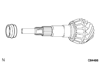
| 36. INSPECT RUNOUT OF DIFFERENTIAL DRIVE PINION |
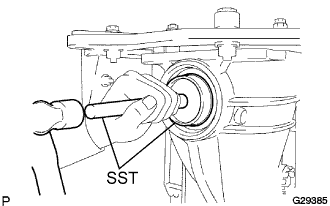
Using a dial indicator, measure the runout of the drive pinion shaft at a position 10 mm (0.39 in.) away from the end of the shaft.
- Maximum runout:
- 0.08 mm (0.0031 in.)
If the runout is greater than the maximum, replace the drive pinion and ring gear.
| 37. INSTALL REAR DRIVE PINION NUT |
Using SST and a hammer, stake the drive pinion nut.
- SST
- 09930-00010
| 38. INSTALL REAR DIFFERENTIAL SIDE GEAR SHAFT OIL SEAL |
Using SST and a hammer, install 2 new oil seals.
- SST
- 09223-15030
09950-70010(09951-07200)
- Oil seal installation depth:
- -0.5 to 0.5 mm (-0.020 to 0.020 in.)
Apply MP grease to the oil seal lips.
| 39. INSTALL REAR DIFFERENTIAL DRAIN PLUG |
Using a hexagon wrench (10 mm), install the differential drain plug with a new gasket.
- Torque:
- 49 N*m{500 kgf*cm, 36 ft.*lbf}
| 40. REMOVE REAR DIFFERENTIAL CARRIER |
Remove the differential carrier from the overhaul attachment.
- NOTICE:
- Clean the fitting surface between the differential carrier and carrier cover.
| 41. INSTALL REAR DIFFERENTIAL BREATHER PLUG OIL DEFLECTOR |
Clean the seal packing attached on the differential carrier and carrier cover using a scraper and wire brush. Then remove the oil with solvent or equivalent.
- NOTICE:
- Do not scratch the sealing surface.
Install the rear differential breather plug oil deflector to the rear differential carrier cover with the bolt.
- Torque:
- 7.0 N*m{70 kgf*cm, 62 in.*lbf}
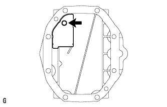
| 42. INSTALL REAR DIFFERENTIAL CARRIER COVER |
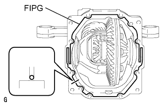
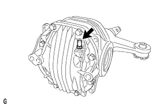
Apply FIPG to the differential carrier at the position shown in the illustration.
- FIPG:
- Toyota Genuine Seal Packing 1281, Three Bond 1281 or equivalent
- NOTICE:
- Apply the seal packing in a continuous bead, approximately 2 to 3 mm (0.08 to 0.12 in.) in diameter.
- Overlap the seal packing at least 10 mm at the beginning and the end of application.
- Install the differential carrier cover within 3 minutes of application.
Install the differential carrier cover with the 8 bolts.
- Torque:
- 47 N*m{475 kgf*cm, 35 ft.*lbf}
- NOTICE:
- Do not fill the differential with oil or drive immediately after installing the differential carrier cover. Allow at least one hour for the sealant to dry before filling the differential. Avoid sudden acceleration and deceleration for at least 12 hours after installation of parts using FIPG sealant.
| 43. INSTALL REAR DIFFERENTIAL CARRIER COVER BREATHER PLUG |
Install the breather plug to the carrier cover.
- Torque:
- 21 N*m{210 kgf*cm, 15 ft.*lbf}