Manual Transmission Assembly Removal
DISCONNECT CABLE FROM NEGATIVE BATTERY TERMINAL
REMOVE NO. 1 ENGINE COVER
REMOVE COOL AIR INTAKE DUCT SEAL
REMOVE ENGINE ROOM SIDE COVER RH
REMOVE POWER STEERING ECU ASSEMBLY
REMOVE BATTERY TRAY
REMOVE SHIFT LEVER KNOB SUB-ASSEMBLY
REMOVE REAR CONSOLE PANEL SUB-ASSEMBLY
REMOVE FRONT CONSOLE PANEL SUB-ASSEMBLY
REMOVE FRONT ASH RECEPTACLE SUB-ASSEMBLY
REMOVE CONSOLE BOX REGISTER ASSEMBLY
REMOVE CONSOLE BOX
REMOVE NO. 2 CONSOLE BOX DUCT
REMOVE NO. 1 SHIFT AND SELECT LEVER BOOT
REMOVE SHIFT LEVER CAP
REMOVE NO. 2 ENGINE UNDER COVER
DRAIN MANUAL TRANSMISSION OIL
REMOVE NO. 1 FLOOR UNDER COVER
REMOVE FRONT FLOOR COVER RH
REMOVE REAR NO. 1 FLOOR PANEL BRACE
REMOVE FRONT CENTER FLOOR BRACE
DISCONNECT AIR FUEL RATIO SENSOR
REMOVE FRONT EXHAUST PIPE ASSEMBLY
REMOVE EXHAUST MANIFOLD CONVERTER SUB-ASSEMBLY
REMOVE FRONT NO. 1 FLOOR HEAT INSULATOR
REMOVE OUTSIDE AIR GUIDE PLATE RH
REMOVE PROPELLER SHAFT WITH CENTER BEARING ASSEMBLY
REMOVE EXHAUST PIPE NO. 1 SUPPORT BRACKET SUB-ASSEMBLY
REMOVE ENGINE UNDER COVER AIR GUIDE BRACKET
REMOVE STARTER ASSEMBLY
REMOVE CLUTCH ACCUMULATOR ASSEMBLY
SEPARATE CLUTCH RELEASE CYLINDER ASSEMBLY
DISCONNECT GROUND CABLE
SEPARATE WIRE HARNESS
SEPARATE FLOOR SHIFT CONTROL SHIFT LEVER RETAINER SUB-ASSEMBLY
REMOVE FLOOR SHIFT LEVER ASSEMBLY
SUPPORT MANUAL TRANSMISSION ASSEMBLY
REMOVE ENGINE REAR MOUNTING MEMBER
REMOVE MANUAL TRANSMISSION ASSEMBLY
REMOVE REAR NO. 1 ENGINE MOUNTING INSULATOR
REMOVE WIRE HARNESS CLAMP BRACKET
Manual Transmission Assembly -- Removal |
| 1. DISCONNECT CABLE FROM NEGATIVE BATTERY TERMINAL |
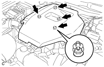
| 2. REMOVE NO. 1 ENGINE COVER |
Remove the No. 1 engine cover.
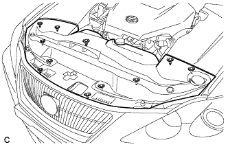
| 3. REMOVE COOL AIR INTAKE DUCT SEAL |
Remove the 11 clips and intake duct seal.
| 4. REMOVE ENGINE ROOM SIDE COVER RH |
Remove the 2 clips and side cover.
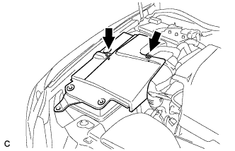
| 5. REMOVE POWER STEERING ECU ASSEMBLY |
(Click here)
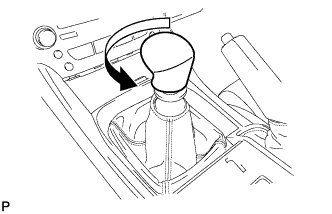
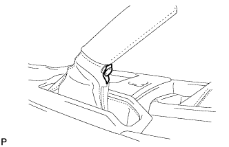
| 7. REMOVE SHIFT LEVER KNOB SUB-ASSEMBLY |
Turn the shift lever knob counterclockwise and remove the shift lever knob sub-assembly.
| 8. REMOVE REAR CONSOLE PANEL SUB-ASSEMBLY |
Open the snap.
Disengage the 7 claws and 2 clips, and then remove the rear console panel sub-assembly.
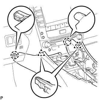
| 9. REMOVE FRONT CONSOLE PANEL SUB-ASSEMBLY |
Open the snap.
Pull the front console panel sub-assembly in the direction indicated by the arrow to disengage the 6 clips and remove it.
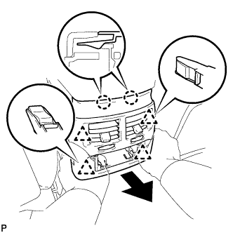
| 10. REMOVE FRONT ASH RECEPTACLE SUB-ASSEMBLY |
Remove the 2 screws <F>.
Pull the front ash receptacle sub-assembly in the direction indicated by the arrow to disconnect the connectors and remove it.
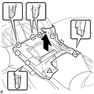
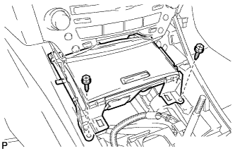
| 11. REMOVE CONSOLE BOX REGISTER ASSEMBLY |
Remove the rear ash receptacle assembly.
Disengage the 2 claws and 4 clips, and then remove the console box register assembly.
Remove the 2 bolts <C>.
Disconnect the 2 connectors.
Disengage the 2 clamps.
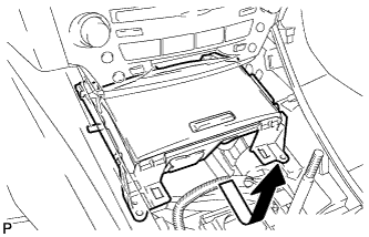
Remove the 2 bolts <C>.
Disconnect the connector.
Remove the 2 bolts <C>.
Disengage the 2 claws and 2 clips, and then remove the console box.
| 13. REMOVE NO. 2 CONSOLE BOX DUCT |
Remove the clip and No. 2 console box duct.
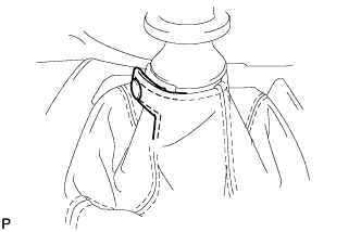
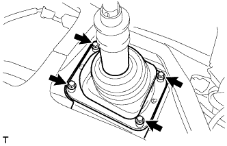
| 14. REMOVE NO. 1 SHIFT AND SELECT LEVER BOOT |
Remove the 4 bolts and No. 1 shift and select lever boot.
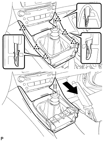
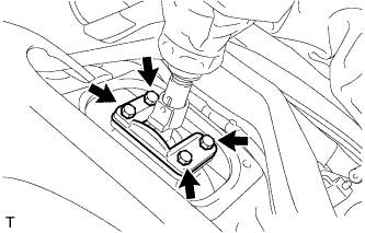
| 15. REMOVE SHIFT LEVER CAP |
Turn over the shift lever dust cover.
Remove the 4 bolts and shift lever cap.
| 16. REMOVE NO. 2 ENGINE UNDER COVER |
| 17. DRAIN MANUAL TRANSMISSION OIL |
Remove the drain plug and gasket, and drain the transmission oil.
Install a new gasket and the drain plug.
- Torque:
- 37 N*m{377 kgf*cm, 27 ft.*lbf}
| 18. REMOVE NO. 1 FLOOR UNDER COVER |
| 19. REMOVE FRONT FLOOR COVER RH |
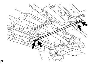
| 20. REMOVE REAR NO. 1 FLOOR PANEL BRACE |
Remove the 4 bolts and rear No. 1 floor panel brace.
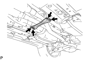
| 21. REMOVE FRONT CENTER FLOOR BRACE |
Remove the 4 bolts and front center floor brace.
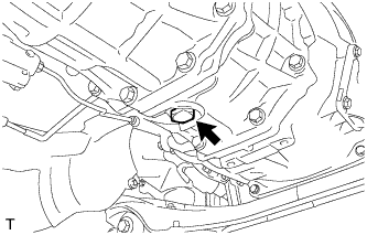
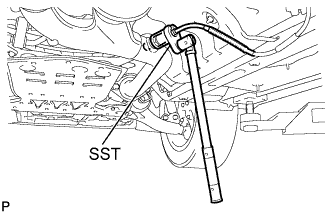
| 22. DISCONNECT AIR FUEL RATIO SENSOR |
Using SST, remove the air fuel ratio sensor.
- SST
- 09224-00010
| 23. REMOVE FRONT EXHAUST PIPE ASSEMBLY |
Remove the 2 bolts and 2 compression springs.
Remove the 2 bolts, 2 compression springs, front exhaust pipe assembly and 2 gaskets.
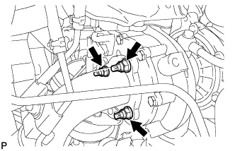
| 24. REMOVE EXHAUST MANIFOLD CONVERTER SUB-ASSEMBLY |
Disconnect the 2 exhaust gas temperature sensor connectors.
Remove the 2 bolts and nut from the No. 1 manifold stay.
Remove the 2 bolts, nut and No. 2 manifold stay.
Using pliers, slide the clip to disconnect the No. 1 and No. 2 vacuum transmitting hose.
Remove the 3 nuts.
Remove the manifold converter sub-assembly and turbine outlet elbow gasket.
Remove the No. 1 manifold stay.
| 25. REMOVE FRONT NO. 1 FLOOR HEAT INSULATOR |
Remove the 4 nuts and front No. 1 floor heat insulator.
| 26. REMOVE OUTSIDE AIR GUIDE PLATE RH |
Remove the 4 nuts and outside air guide plate RH.
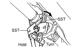
| 27. REMOVE PROPELLER SHAFT WITH CENTER BEARING ASSEMBLY |
Using SST, loosen the adjusting nut until it can be turned by hand.
- SST
- 09922-10010
- HINT:
- Use 2 of the same type of SST.
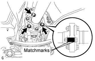
Put matchmarks on the transmission companion flange, flexible coupling and intermediate shaft.
Remove the 3 bolts, 3 washers and 3 nuts.
- NOTICE:
- The propeller shaft and flexible coupling should not be separated.
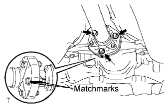
Put matchmarks on the differential companion flange, flexible coupling and propeller shaft.
Remove the 3 bolts, 3 washers and 3 nuts.
- NOTICE:
- The propeller shaft and flexible coupling should not be separated.
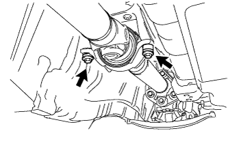
Remove the 2 bolts, 2 center support bearing washers and 2 center support bearing dampers.
- HINT:
- Some vehicles are not equipped with the center support bearing washers.
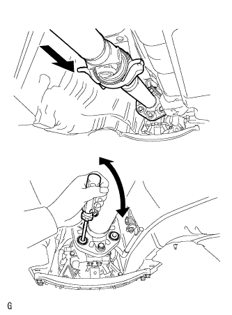
Push the rear propeller shaft straight ahead to compress and pull out the propeller shaft from the centering pin of the differential.
- NOTICE:
- Press the propeller shaft straight ahead to keep the transmission and intermediate shaft aligned straight.
- HINT:
- If it is difficult to separate the flange from the flexible coupling, pry it using a screwdriver.
Pull the propeller shaft outward from the rear of the vehicle.
- NOTICE:
- The intermediate shaft and propeller shaft should not be separated.
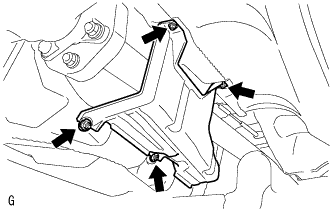
| 28. REMOVE EXHAUST PIPE NO. 1 SUPPORT BRACKET SUB-ASSEMBLY |
Remove the 2 nuts and exhaust pipe No. 1 support bracket sub-assembly.
| 29. REMOVE ENGINE UNDER COVER AIR GUIDE BRACKET |
Remove the 2 bolts and engine under cover air guide bracket.
| 30. REMOVE STARTER ASSEMBLY |
(Click here)
| 31. REMOVE CLUTCH ACCUMULATOR ASSEMBLY |
(Click here)
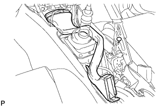
| 32. SEPARATE CLUTCH RELEASE CYLINDER ASSEMBLY |
(Click here)
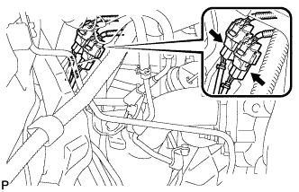
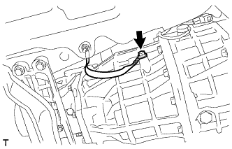
| 33. DISCONNECT GROUND CABLE |
Remove the bolt and disconnect the ground cable.
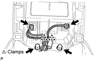
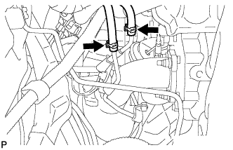
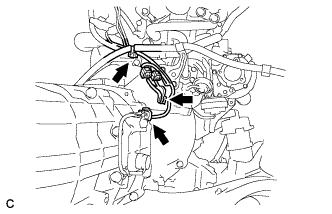
| 34. SEPARATE WIRE HARNESS |
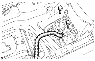
Remove the bolt and separate the wire harness bracket.
Disconnect the back-up light switch connector and separate the wire harness.
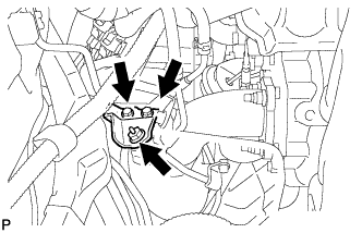
| 35. SEPARATE FLOOR SHIFT CONTROL SHIFT LEVER RETAINER SUB-ASSEMBLY |
Remove the 2 nuts and separate the floor shift control shift lever retainer sub-assembly.
| 36. REMOVE FLOOR SHIFT LEVER ASSEMBLY |
Turn over the shift and select lever boot.
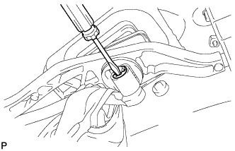
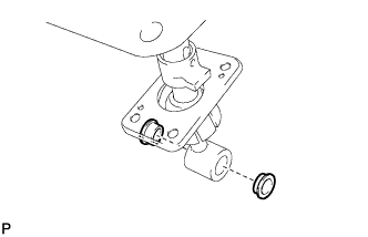
Using a screwdriver, remove the E-ring and floor shift lever assembly.
Remove the washer from the floor shift lever assembly.
Remove the 2 bushings from the floor shift lever assembly.
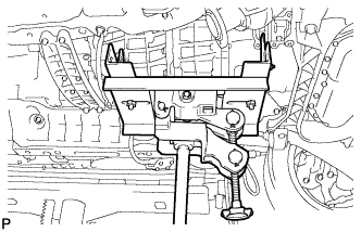
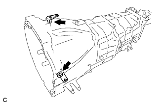
| 37. SUPPORT MANUAL TRANSMISSION ASSEMBLY |
Support the manual transmission with a transmission jack.
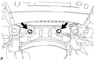
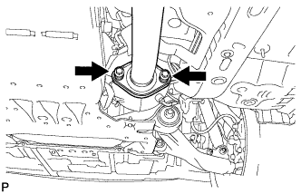
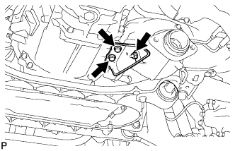
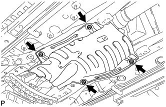
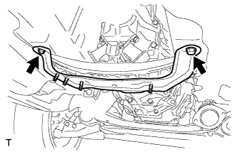
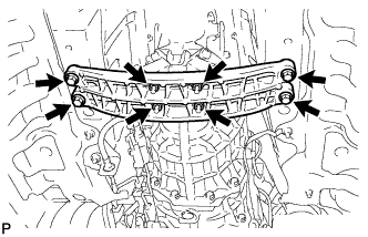
| 38. REMOVE ENGINE REAR MOUNTING MEMBER |
Remove the 4 bolts, 4 nuts, and engine rear mounting member.
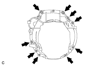
| 39. REMOVE MANUAL TRANSMISSION ASSEMBLY |
Remove the 9 bolts and manual transmission assembly.
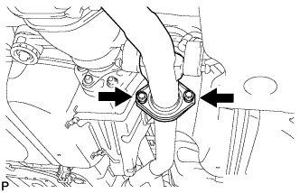
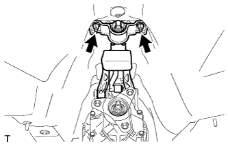
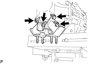
| 40. REMOVE REAR NO. 1 ENGINE MOUNTING INSULATOR |
Remove the 4 bolts and rear No. 1 engine mounting insulator.
| 41. REMOVE WIRE HARNESS CLAMP BRACKET |
Remove the 2 bolts and 2 wire harness clamp brackets.