Automatic Transmission System Shift Paddle Switch Circuit
DESCRIPTION
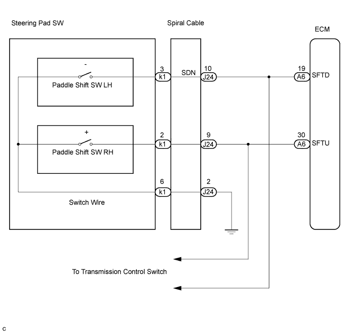
WIRING DIAGRAM
INSPECTION PROCEDURE
CHECK HARNESS AND CONNECTOR (SPIRAL CABLE - BODY GROUND)
INSPECT SPIRAL CABLE SUB-ASSEMBLY
INSPECT TRANSMISSION SHIFT SWITCH ASSEMBLY
INSPECT SWITCH WIRE
CHECK HARNESS AND CONNECTOR (SPIRAL CABLE - ECM)
AUTOMATIC TRANSMISSION SYSTEM - Shift Paddle Switch Circuit |
DESCRIPTION
When moving the shift lever into the S position using the transmission control switch, it is possible to switch the shift range position between "1" (first range) and "6" (sixth range).Shifting up "+" once raises one shift range position, and shifting down "-" lowers one shift range position.
WIRING DIAGRAM
INSPECTION PROCEDURE
| 1.CHECK HARNESS AND CONNECTOR (SPIRAL CABLE - BODY GROUND) |
Disconnect the steering pad switch connector and spiral cable connector.
Measure the resistance according to the value(s) in the table below.
- Standard resistance:
Tester Connection
| Specified Condition
|
2 - Body ground
| Below 1 Ω
|
| | REPAIR OR REPLACE HARNESS OR CONNECTOR |
|
|
| 2.INSPECT SPIRAL CABLE SUB-ASSEMBLY |
Measure the resistance according to the value(s) in the table below.
- Standard resistance:
Tester Connection
| Condition
| Specified Condition
|
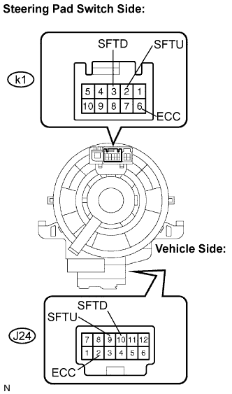
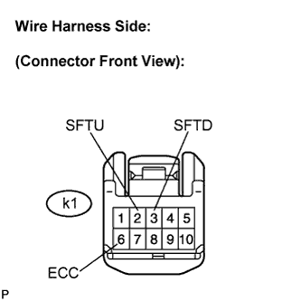
J24-2 - k1-6
| Always
| Below 1 Ω
|
J24-9 - k1-2
| Always
| Below 1 Ω
|
J24-10 - k1-3
| Always
| Below 1 Ω
|
| | REPLACE SPIRAL CABLE SUB-ASSEMBLY |
|
|
| 3.INSPECT TRANSMISSION SHIFT SWITCH ASSEMBLY |
Disconnect the switch wire connector from the transmission shift switch.
Measure the resistance between each terminal when the paddle shift is moved to each position.
- Standard resistance:
Paddle Shift Position
| Tester Connection
| Specified Condition
|
Pull continuously
"+"
(Up shift)
| SFTU - ECC
| Below 1 Ω
|
Release
"+"
(Up shift)
| ↑
| 10 kΩ or higher
|
Pull continuously
"-"
(Down shift)
| SFTD - ECC
| Below 1 Ω
|
Release
"-"
(Down shift)
| ↑
| 10 kΩ or higher
|
| | REPLACE TRANSMISSION SHIFT SWITCH ASSEMBLY |
|
|
Connect the switch wire connector to the transmission shift switch.
Measure the resistance between each terminal when the paddle shift is moved to each position.
- Standard resistance:
Paddle Shift Position
| Tester Connection
| Specified Condition
|
Pull continuously
"+"
(Up shift)
| 2 - 6
| Below 1 Ω
|
Release
"+"
(Up shift)
| ↑
| 10 kΩ or higher
|
Pull continuously
"-"
(Down shift)
| 3 - 6
| Below 1 Ω
|
Release
"-"
(Down shift)
| ↑
| 10 kΩ or higher
|
| 5.CHECK HARNESS AND CONNECTOR (SPIRAL CABLE - ECM) |
Connect the spiral cable connector and steering pad switch connector.
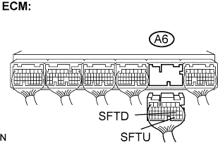
Disconnect the ECM connector.
Measure the resistance according to the value(s) in the table below when the paddle shift is moved to each position.
- Standard resistance:
Paddle Shift Position
| Tester Connection
| Specified Condition
|
Pull continuously
"+"
(Up shift)
| A6-30 (SFTU) - Body ground
| Below 1 Ω
|
Release
"+"
(Up shift)
| ↑
| 10 kΩ or higher
|
Pull continuously
"-"
(Down shift)
| A6-19 (SFTD) - Body ground
| Below 1 Ω
|
Release
"-"
(Down shift)
| ↑
| 10 kΩ or higher
|
| | REPAIR OR REPLACE HARNESS OR CONNECTOR |
|
|
| OK |
|
|
|
| PROCEED TO NEXT CIRCUIT INSPECTION SHOWN IN PROBLEM SYMPTOMS TABLE |
|