Dtc B2276 Accr Signal Circuit Malfunction
Engine. Lexus Is250, Is220D. Gse20 Ale20
DESCRIPTION
WIRING DIAGRAM
INSPECTION PROCEDURE
CHECK CONNECTORS
CHECK WIRE HARNESS (POWER SOURCE CONTROL ECU - BODY GROUND)
CHECK WIRE HARNESS (POWER SOURCE CONTROL ECU - ECM)
INSPECT ECM
INSPECT POWER SOURCE CONTROL ECU
DTC B2276 ACCR Signal Circuit Malfunction |
DESCRIPTION
This DTC is output when the ACCR output circuits inside the power source control ECU are open or short.- HINT:
- When the power source control ECU is replaced with a new one and the negative (-) battery terminal is connected, the power source mode becomes the IG-ON mode. When the battery is removed and reinstalled, the power source mode that was selected when the battery was removed is restored.
DTC No.
| DTC Detection Condition
| Trouble Area
|
B2276
| ACCR output circuit inside power source control ECU or other related circuit is malfunctioning
| - Power source control ECU
- ECM
- Wire harness or connector
|
WIRING DIAGRAM
INSPECTION PROCEDURE
Check that the connectors are securely connected and the terminals are not deformed or loose.
- OK:
- The connectors are securely connected and the terminals are not deformed or loose.
| | REPAIR OR REPLACE CONNECTORS |
|
|
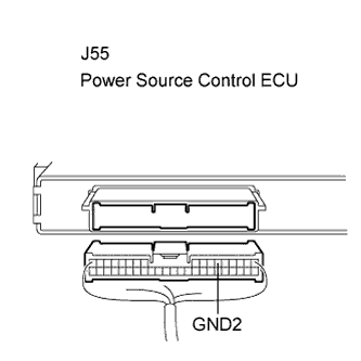
| 2.CHECK WIRE HARNESS (POWER SOURCE CONTROL ECU - BODY GROUND) |
Disconnect the J55 ECU connector.
Measure the resistance according to the value(s) in the table below.
- Standard resistance:
Tester Connection (Symbols)
| Condition
| Specified Condition
|
J55-6 (GND2) - Body ground
| Always
| Below 1 Ω
|
| | REPAIR OR REPLACE HARNESS OR CONNECTOR |
|
|
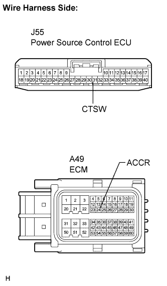
| 3.CHECK WIRE HARNESS (POWER SOURCE CONTROL ECU - ECM) |
Disconnect the A49 ECM connector.
Measure the resistance according to the value(s) in the table below.
- Standard resistance:
Tester Connection (Symbols)
| Condition
| Specified Condition
|
J55-31 (CTSW) - A49-24 (ACCR)
| Always
| Below 1 Ω
|
J55-31 (CTSW) or A49-24 (ACCR) - Body ground
| Always
| 10 kΩ or higher
|
| | REPAIR OR REPLACE HARNESS OR CONNECTOR |
|
|
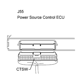
Reconnect the A49 ECM connector.
Measure the voltage according to the value(s) in the table below.
- Standard voltage:
Tester Connection (Symbols)
| Condition
| Specified Condition
|
J55-31 (CTSW) - Body ground
| Always
| 8 to 14 V
|
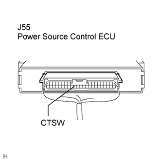
| 5.INSPECT POWER SOURCE CONTROL ECU |
Reconnect the J55 ECU connector.
Measure the voltage according to the value(s) in the table below.
- Standard voltage:
Terminal No. (Symbol)
| Condition
| Specified condition
|
J55-31 (CTSW) - Body ground
| Clutch pedal depressed, Engine switch on (ST) → on (IG)
| 0.1 to 0.8 V (*1) →
Output voltage at terminal AM2 is -2 V or more.
|
- HINT:
- *1: Voltage is output only when the engine is cranking.
| | REPLACE POWER SOURCE CONTROL ECU |
|
|
| OK |
|
|
|
| CHECK INTERMITTENT PROBLEMS |
|