Exhaust Gas Temperature Sensor Installation
Engine. Lexus Is250, Is220D. Gse20 Ale20
INSTALL EXHAUST GAS TEMPERATURE SENSOR (LOWER)
INSTALL EXHAUST GAS TEMPERATURE SENSOR (UPPER)
INSTALL EXHAUST MANIFOLD CONVERTER SUB-ASSEMBLY
INSTALL FRONT EXHAUST PIPE ASSEMBLY
INSTALL BATTERY TRAY
INSTALL POWER STEERING ECU ASSEMBLY
CHECK FOR EXHAUST GAS LEAKS
INSTALL ENGINE ROOM SIDE COVER RH
INSTALL COOL AIR INTAKE DUCT SEAL
INSTALL NO. 1 ENGINE COVER
Exhaust Gas Temperature Sensor -- Installation |
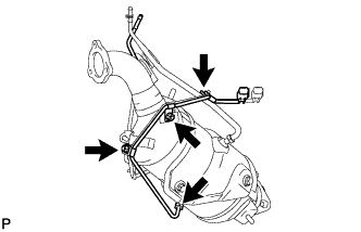
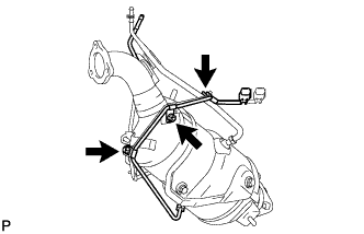
| 1. INSTALL EXHAUST GAS TEMPERATURE SENSOR (LOWER) |
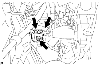
Temporarily install the exhaust gas temperature sensor (lower) with the 2 nuts.
Tighten the 2 nuts.
- Torque:
- 6.4 N*m{65 kgf*cm, 57 in.*lbf}
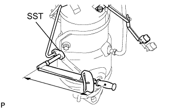
Using SST, tighten the nut of the exhaust gas temperature sensor (lower).
- SST
- 09023-38401
- Torque:
- 30 N*m{306 kgf*cm, 22 ft.*lbf}
- HINT:
- Use a torque wrench with a fulcrum length of 30 cm (11.81 in.).
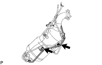
| 2. INSTALL EXHAUST GAS TEMPERATURE SENSOR (UPPER) |
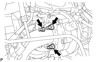
Temporarily install the exhaust gas temperature sensor (upper) with the 3 nuts.
Tighten the 3 nuts.
- Torque:
- 6.4 N*m{65 kgf*cm, 57 in.*lbf}
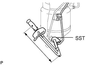
Using SST, tighten the nut of the exhaust gas temperature sensor (upper).
- SST
- 09023-38401
- Torque:
- 30 N*m{306 kgf*cm, 22 ft.*lbf}
- HINT:
- Use a torque wrench with a fulcrum length of 30 cm (11.81 in.).
| 3. INSTALL EXHAUST MANIFOLD CONVERTER SUB-ASSEMBLY |
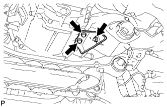
Temporarily install the No. 1 manifold stay.
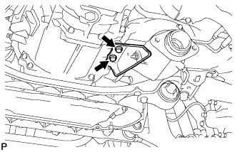
Temporarily install a new turbine outlet elbow gasket and exhaust manifold converter with the 3 nuts.
Temporarily install the 2 bolts and nut.
Tighten the 3 nuts (Pushing the manifold converter against the No. 1 manifold stay).
- Torque:
- 25 N*m{255 kgf*cm, 18 ft.*lbf}
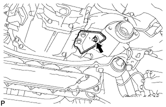
Tighten the 2 bolts and nut.
- Torque:
- 56 N*m{571 kgf*cm, 41 ft.*lbf}
Temporarily install the No. 2 exhaust manifold stay with the 2 bolts and nut.
Tighten the 2 bolts (Pushing the No. 2 exhaust manifold stay against the manual transmission).
- Torque:
- 56 N*m{571 kgf*cm, 41 ft.*lbf}
Tighten the nut.
- Torque:
- 56 N*m{571 kgf*cm, 41 ft.*lbf}
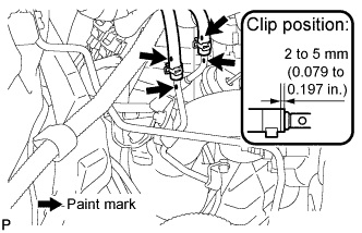
Using pliers, slide the clip to install the No. 1 and No. 2 vacuum transmitting hose assembly.
- HINT:
- Make sure that the paint marks on the No. 1 and No. 2 vacuum transmitting hose assemblies and No. 1 and No. 2 vacuum pipes are aligned.
| 4. INSTALL FRONT EXHAUST PIPE ASSEMBLY |
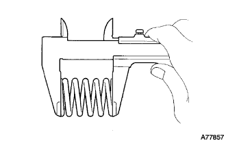
Using vernier calipers, measure the free length of the compression springs.
- Minimum length:
- 38.5 mm (1.516 in.)
If the free length is less than the minimum, replace the compression spring.
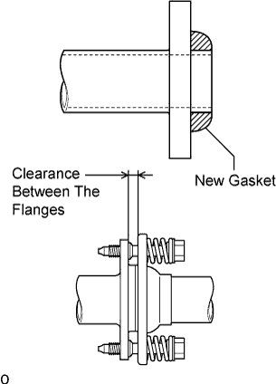
Fully insert 2 new gaskets to the exhaust manifold converter and front exhaust pipe assembly by hand.
- NOTICE:
- Be careful with the installation direction of the gasket.
- Do not reuse the gasket.
- Do not damage the gasket.
- To ensure a proper seal, do not use the tail exhaust pipe to force the gasket onto the front exhaust pipe.
- HINT:
- Using a plastic hammer, uniformly strike the gasket so that the gasket and front exhaust pipe are properly fit.
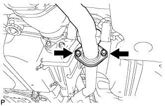
Install the front exhaust pipe assembly.
Install the 2 bolts and 2 compression springs.
- Torque:
- 43 N*m{439 kgf*cm, 32 ft.*lbf}
- NOTICE:
- After installation, check that the clearance is almost the same at any point between the flanges of the tail exhaust pipe assembly and front exhaust pipe assembly.
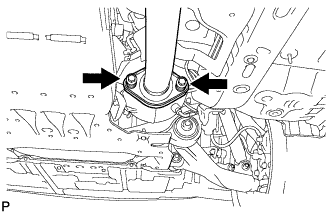
Install the 2 bolts and 2 compression springs.
- Torque:
- 43 N*m{439 kgf*cm, 32 ft.*lbf}
- NOTICE:
- After installation, check that the clearance is almost the same at any point between the flanges of the exhaust manifold converter and front exhaust pipe assembly.
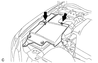
| 6. INSTALL POWER STEERING ECU ASSEMBLY |
- HINT:
- (Click here)
| 7. CHECK FOR EXHAUST GAS LEAKS |
If exhaust gas is leaking, tighten the related parts to stop the leak. Replace damaged parts as necessary.
| 8. INSTALL ENGINE ROOM SIDE COVER RH |
Install the side cover with the 2 clips.
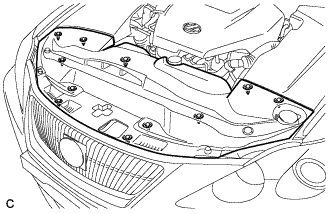
| 9. INSTALL COOL AIR INTAKE DUCT SEAL |
Install the intake duct seal with the 11 clips.
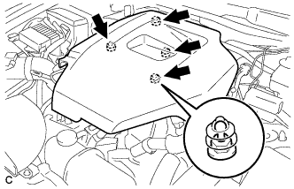
| 10. INSTALL NO. 1 ENGINE COVER |
Install the No. 1 engine cover.